Frequency-and-pattern-reconfigurable antenna based on liquid crystal material

A technology of liquid crystal material and direction diagram, which is applied in the direction of antenna, antenna support/installation device, antenna grounding switch structure connection, etc., can solve the problems of large size and complex structure, and achieve simple structure, small volume and high reliability Effect

Inactive Publication Date: 2016-08-24
UNIV OF ELECTRONICS SCI & TECH OF CHINA
View PDF2 Cites 28 Cited by
  • Summary
  • Abstract
  • Description
  • Claims
  • Application Information

AI Technical Summary

Problems solved by technology

[0007] The present invention aims at the problems of large size and complicated structure in the prior art of reconfigurable antennas, and proposes a frequency and pattern reconfigurable antenna based on liquid crystal material

Method used


Image

  • Frequency-and-pattern-reconfigurable antenna based on liquid crystal material
  • Frequency-and-pattern-reconfigurable antenna based on liquid crystal material
  • Frequency-and-pattern-reconfigurable antenna based on liquid crystal material

Examples


Embodiment 1

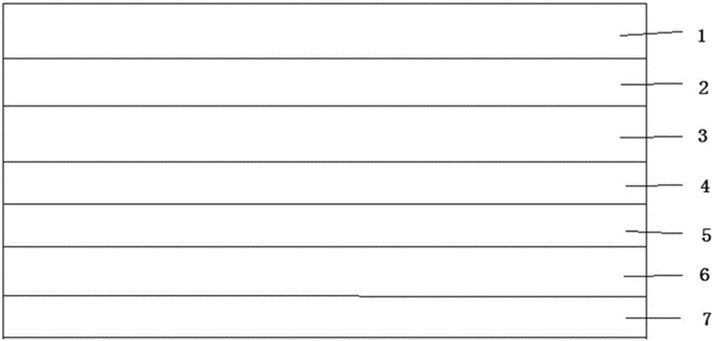
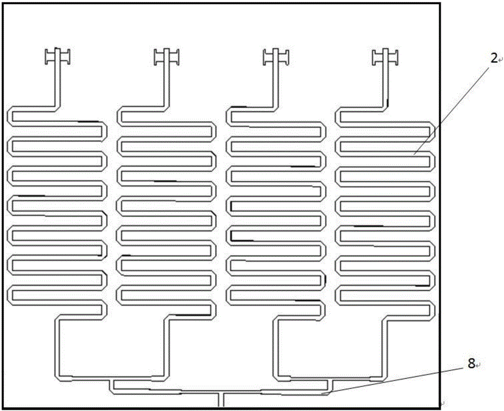
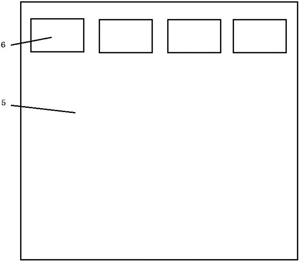
[0020] Embodiment 1: A frequency and pattern reconfigurable antenna based on liquid crystal material, the antenna includes: a liquid crystal phase shifter, a liquid crystal microstrip antenna; the liquid crystal phase shifter includes: an upper glass substrate, one or more snakes Shaped metal delay line, liquid crystal material, metal floor, liquid crystal packaging structure, wherein the snake-shaped metal delay line is located on the lower surface of the upper glass substrate, and the end of the snake-shaped metal delay line is a straight line, one end of which is flush with the glass substrate for Feeding, liquid crystal material is set between the upper glass substrate and the metal floor, and the liquid crystal packaging structure is located around the liquid crystal phase shifter to seal the liquid crystal material; the liquid crystal microstrip antenna includes: metal floor, liquid crystal material, one or more pieces as antenna The number of metal patches of the radiati...


PUM


Abstract

The invention belongs to the antenna technical field and specifically relates to a frequency-and-pattern-reconfigurable antenna based on a liquid crystal material. The frequency-reconfigurable antenna comprises a liquid crystal phase shifter, a liquid crystal microstrip antenna and a one-to-four power divider. By combining the electrical regulation and control characteristic of the liquid crystal material and the design of the frequency-and-pattern-reconfigurable antenna, the frequency-and-pattern-reconfigurable antenna based on the liquid crystal material is produced, so that the frequency of the antenna can realize continuous regulation, tuning range is large and wave beams are deflectable; and practical application of the frequency-and-pattern-reconfigurable antenna in the aspects of miniaturization and broadband is improved.

Description

technical field [0001] The invention belongs to the technical field of antennas, and in particular relates to a reconfigurable antenna of frequency and pattern based on liquid crystal material. Background technique [0002] With the rapid development of modern radar and communication systems, in order to achieve communication, navigation, guidance, warning, weapon homing and other purposes, the number of antennas required by aircraft, ships, satellites, etc. is increasing. This increases the weight of the platform and the cost of building the antennas. At the same time, the electromagnetic interference between the antennas is also very large, which seriously affects the normal operation of the antennas. In order to reduce the weight of the antenna loaded on the platform, reduce the cost, reduce the radar cross section of the platform, and achieve good electromagnetic compatibility, it is hoped that one antenna can realize the functions of multiple antennas. Using the same a...

Claims


Application Information

Patent Timeline
Patent Type & Authority Applications(China)
IPC IPC(8): H01Q3/44H01Q1/22H01Q1/50
CPCH01Q1/22H01Q1/50H01Q3/44
Inventor 赵怿哲赵青
Owner UNIV OF ELECTRONICS SCI & TECH OF CHINA
Why Eureka
Try Eureka