Normally-closed moisture-proof power distribution cabinet

A power distribution cabinet and normally closed technology, which is applied in the field of power distribution cabinets with lockable doors, can solve the problems of complex structure of the cabinet door locking device, complicated opening or closing of the cabinet door, and poor locking performance of the cabinet door. , to achieve the effect of simple structure, good locking performance and improved efficiency

Inactive Publication Date: 2016-08-24
新都区大丰鹏宇机械厂
View PDF2 Cites 5 Cited by
  • Summary
  • Abstract
  • Description
  • Claims
  • Application Information

AI Technical Summary

Problems solved by technology

However, the above two power distribution cabinets, like the existing power distribution cabinets, have defects such as complex structure of the cabinet door locking device, high production cost, complicated opening or closing of the cabinet door, and poor locking performance of the cabinet door.

Method used


Image

  • Normally-closed moisture-proof power distribution cabinet
  • Normally-closed moisture-proof power distribution cabinet
  • Normally-closed moisture-proof power distribution cabinet

Examples


Embodiment 1

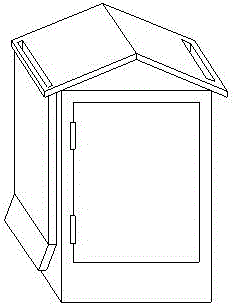
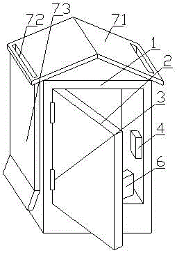
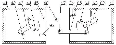
[0027] A normally closed moisture-proof power distribution cabinet, including a cabinet body 1 and a cabinet door 2, the cabinet body 1 and the cabinet door 2 are pivotally connected through a pivot joint device 3, so that the cabinet door 2 can rotate freely on the cabinet body 1 to realize Opening or closing of cabinet door 2. The inner wall of the cabinet door 2 is connected with a first locking part 6, and the inner wall of the cabinet body 1 is connected with a second locking part 4, and the first locking part 6 is matched with the second locking part 4, The cabinet door 2 can be locked on the cabinet body 1 through the first locking component 6 and the second locking component 4 . The second locking part 4 includes a second lock body 41 fixedly connected to the cabinet body 1, a cavity is opened in the second lock body 41, and a second swinging part 43 is hinged in the cavity of the second lock body 41. , the second swing member 43 can rotate in the second lock body 41 ...

Embodiment 2

[0034] On the basis of the first embodiment, there are at least three pivot rings 2 on the left blade 1 , and a plurality of pivot rings 2 are evenly arranged along the axial direction of the pivot device 3 . By setting multiple sets of pivot rings 2, the connection stability of the pivot ring 2 sleeved on the pivot device 3 can be improved, so that when the pivot ring 2 or the pivot device 3 is rotated, the pivot ring 2 and the pivot The devices 3 can rotate mutually smoothly.

Embodiment 3

[0036] On the basis of Embodiment 1 or Embodiment 2, in order to facilitate the smooth introduction of the snap-fit ​​shaft on the connecting rod into the corresponding snap-fit ​​groove, a part of the second lock body 41 close to the second snap-fit ​​groove 44 The side is provided with a second guide block 47, when in the process of locking the cabinet door 2, the first connecting rod 65 moves to the side close to the second guide block 47, when the first connecting rod 65 moves to the second guide block 47 , the second guide block 47 can smoothly guide the first engaging shaft of the first connecting rod 65 into the second engaging groove 47 .

[0037] A first guide block 67 is provided on the side close to the first engagement groove 64 in the first lock body 61 , and when the cabinet door 2 is locked, the second connecting rod 45 moves toward a side close to the first guide block 67 . side movement, when the second connecting rod 45 moves to the first guiding block 67 , t...


PUM


Abstract

The invention discloses a normally-closed moisture-proof power distribution cabinet, belongs to the technical field of power distribution cabinets, and aims to provide a normally-closed moisture-proof power distribution cabinet with high locking performance. The normally-closed moisture-proof power distribution cabinet comprises a cabinet body and a cabinet door, wherein the cabinet body is in a pivoting connection with the cabinet door through a pivoting device; an inner wall of the cabinet door is connected with a first locking component; an inner wall of the cabinet body is connected with a second locking component which is matched with the first locking component; the pivoting device comprises a left blade which is fixedly connected to the cabinet body, and a right blade which is fixedly connected to the cabinet door; the left blade is provided with a pivoting ring; the right blade is connected with the pivoting device; the pivoting ring sleeves the pivoting device; a reset mechanism for driving the cabinet door to be closed normally is further arranged between the pivoting ring and the pivoting device; a flashing board is arranged above a top surface of the cabinet body; a cross section of the flashing board is triangular; both sides of the flashing board are provided with rectangular draining holes along a width direction of the flashing board; the draining holes communicate below with downpipes; and the downpipes are fixedly connected on a side wall of the cabinet body. The normally-closed moisture-proof power distribution cabinet is suitable for power distribution cabinets.

Description

technical field [0001] The invention belongs to the technical field of power distribution cabinets, and relates to a power distribution cabinet with lockable cabinet doors. Background technique [0002] In addition to satisfying normal use, the existing power distribution cabinets also need to be closed and locked. Existing power distribution cabinets either use latches to lock the cabinet doors after closing the cabinet doors, or use locks such as mechanical locks or electronic locks to lock the cabinet doors. [0003] The invention patent with application number 201520025988.7 discloses a power distribution cabinet, which includes a cabinet door with a door lock and a lock hole for the key to be inserted into. The top of the lock hole is provided with a button. A buzzer is provided, and the button is coupled with a control circuit for controlling the response of the buzzer. In the power distribution cabinet, when the key is inserted into the lock hole, the button is pres...

Claims


Application Information

Patent Timeline
IPC IPC(8): H02B1/28H02B1/30
CPCH02B1/28H02B1/30
Inventor 刘泽刚
Owner 新都区大丰鹏宇机械厂
Why Eureka
Try Eureka