Intelligent digital drilling panoramic camera device

A panoramic camera and digital technology, which is applied to the device for taking pictures of boreholes and the field of intelligent digital panoramic camera devices for boreholes, can solve the problems of inability to calculate and analyze, dangerous, and consumes a lot of physical strength and time, and achieves the realization of Remote operation, improved safety, wide range of effects

Active Publication Date: 2019-06-28
INST OF ROCK & SOIL MECHANICS CHINESE ACAD OF SCI
View PDF4 Cites 0 Cited by
  • Summary
  • Abstract
  • Description
  • Claims
  • Application Information

AI Technical Summary

Problems solved by technology

[0004] As the buried depth of rock mass engineering increases, high ground stress disasters and high radioactive pollution become more and more serious, which poses a great threat to the life safety of drilling personnel.
There are great dangers in the construction and testing of the above-mentioned rock mass engineering. In this environment, when using conventional drilling cameras to observe the deformation and damage of the surrounding rock, the life safety of the operators is facing a great threat.
At the same time, the existing borehole camera can only be applied to the detection of one aperture, and cannot be applied to boreholes with multiple apertures
In addition, the existing borehole camera needs to use several connecting rods to continuously push the borehole camera instrument into the borehole to obtain the surrounding rock information of the borehole wall in the direction of the entire borehole axis, which requires a lot of physical strength and time.
Finally, the existing borehole camera devices can only be used to observe geological phenomena in boreholes, and cannot accurately calculate and analyze them (such as determining the occurrence, spacing, and gap width of structural planes, etc.), and cannot perform More in-depth statistics and analysis

Method used


Image

  • Intelligent digital drilling panoramic camera device
  • Intelligent digital drilling panoramic camera device
  • Intelligent digital drilling panoramic camera device

Examples


Embodiment Construction

[0021] The implementation of the present invention will be described in detail below in conjunction with the accompanying drawings, but they do not constitute a limitation to the present invention, and are only examples. At the same time, the advantages of the present invention are clearer and easier to understand through the description.

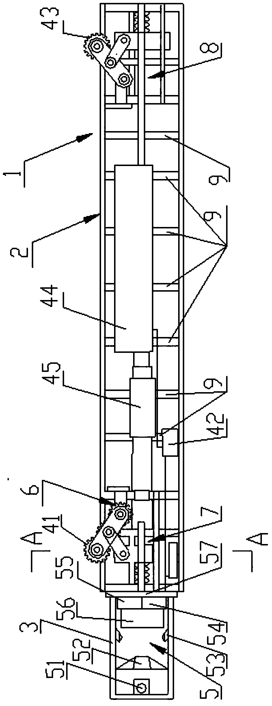
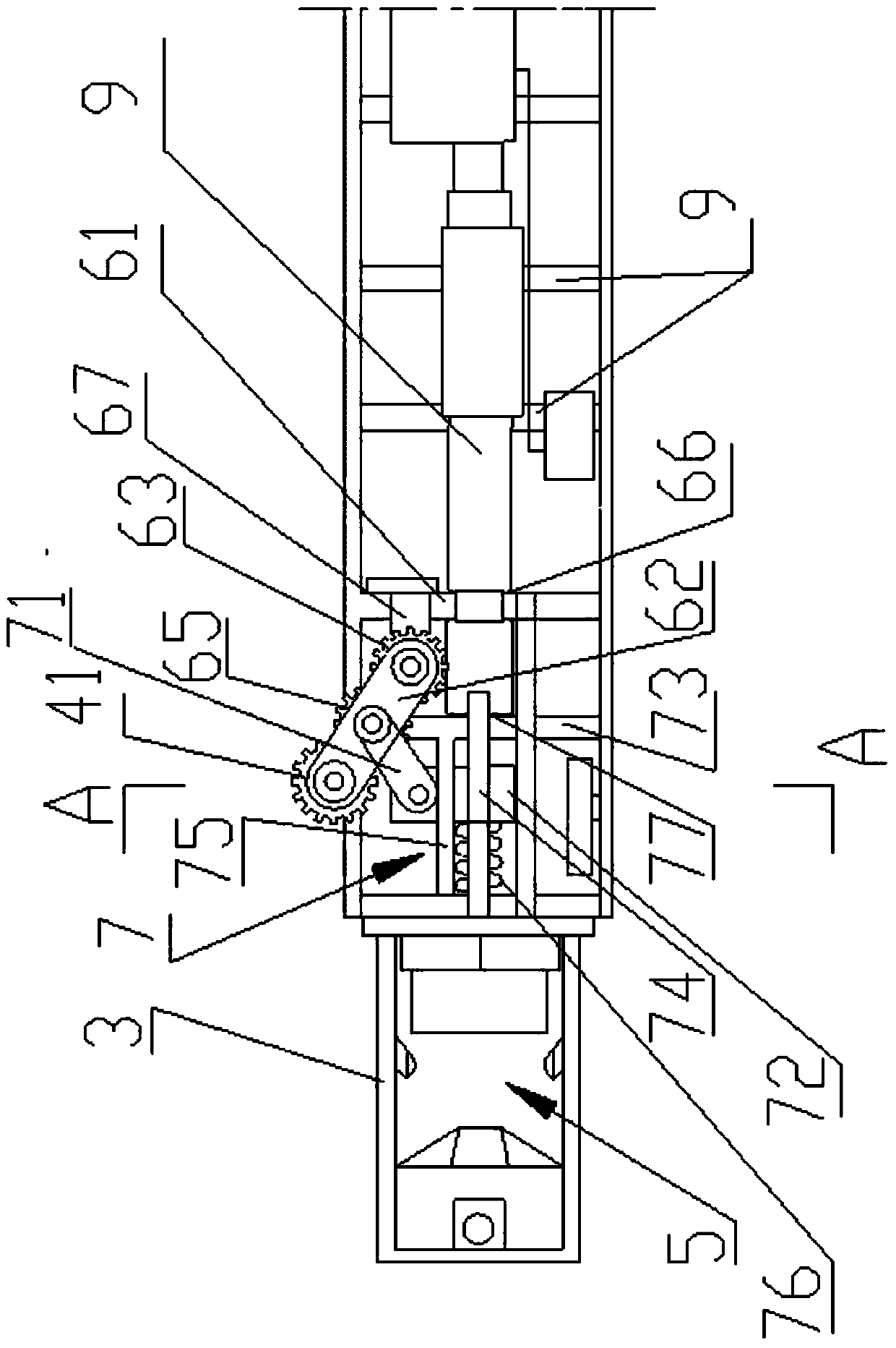
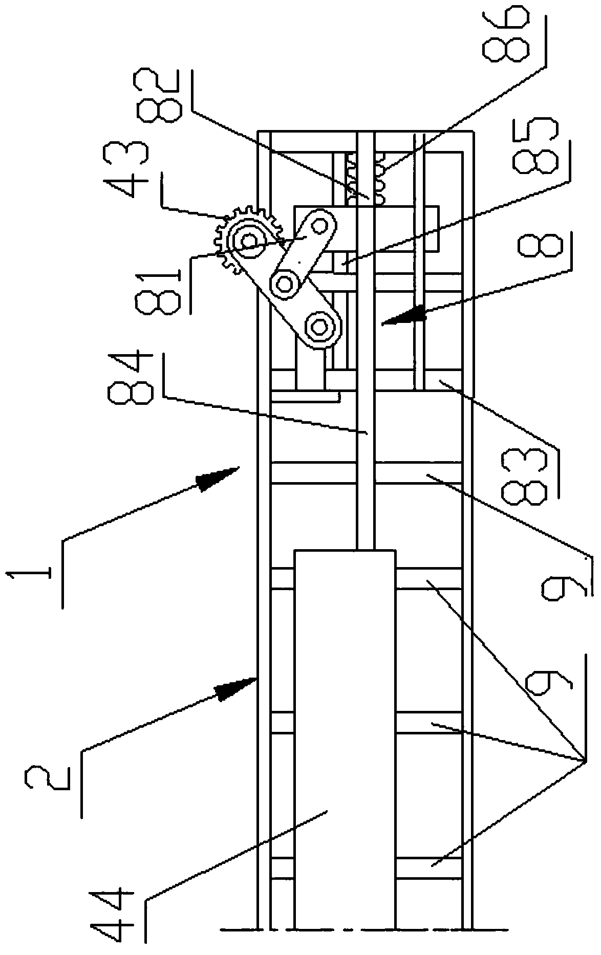
[0022] Referring to the accompanying drawings, it can be seen that the intelligent digital drilling panoramic camera device includes a device body 1, and the device body 1 includes a waterproof casing 2, a transparent tube 3 installed on the outer front end of the waterproof casing 2, and a transparent tube installed on the waterproof casing 2. Internal battery 42, a plurality of driving wheels 41 positioned at the front end of the waterproof casing 2, a plurality of driven wheels 43 positioned at the rear end of the waterproof casing 2, and a motor 44 positioned at the inside of the waterproof casing 2; Hole carries out the panorama camera...


PUM


Abstract

The invention discloses an intelligent digital drilling panoramic camera device, which relates to a device for taking pictures of boreholes in rock mass engineering. It includes a device body, a waterproof case, a transparent tube, a battery, a driving wheel, a driven wheel, and a motor; a panoramic camera mechanism is installed in the transparent tube, the output end of the battery is connected to the motor, and the output end of the motor is connected to the drive through the front wheel drive mechanism. The wheel is connected; the front wheel diameter reducing mechanism is installed between the driving wheel and the waterproof casing, and the rear wheel diameter reducing mechanism is installed between the driven wheel and the waterproof casing; the panoramic camera mechanism, the front wheel driving mechanism, the front wheel diameter reducing mechanism Both the mechanism and the reducing mechanism of the rear wheel are wirelessly connected with the analysis control system located on the ground. The invention has a wide application range, can be applied to borehole camera observation of various apertures, is convenient to operate, is convenient and intelligent, has high safety, and integrates borehole camera observation and information processing.

Description

technical field [0001] The invention belongs to the technical field of rock mass engineering borehole camera technology, and relates to a device for photographing boreholes in rock mass engineering, in particular to an intelligent digital borehole panoramic camera device. Background technique [0002] With the rapid development of my country's national economy, large-scale rock mass engineering construction is emerging, such as tunnels, water storage dams, underground mine shafts, hydropower diversion tunnels, underground powerhouses, and nuclear waste disposal warehouses. The structural stability of the above-mentioned rock mass engineering during construction and operation is the most concerned issue for rock mechanics workers, and the deformation characteristics and laws of rock mass are the direct reflection of judging whether the surrounding rock is in a safe and stable state. Most of the key parts of rock mass deformation and failure are located on discontinuous struct...

Claims


Application Information

Patent Timeline
Patent Type & Authority Patents(China)
IPC IPC(8): H04N7/18H04N5/225
CPCH04N7/183H04N23/555H04N23/50
Inventor 周辉黄磊卢景景张传庆胡大伟胡明明高阳刘海涛
Owner INST OF ROCK & SOIL MECHANICS CHINESE ACAD OF SCI
Why Eureka
Try Eureka