An energy-saving multi-rotor UAV device based on bionic suspension

A multi-rotor unmanned aerial vehicle, unmanned aerial vehicle technology, applied in the direction of rotorcraft, unmanned aerial vehicle, motor vehicle, etc., can solve the problems of power consumption, hovering function failure, unsuitable use, etc., and achieves broad application prospects, The effect of simple recovery device and simple structure

Active Publication Date: 2018-03-06
THE 28TH RES INST OF CHINA ELECTRONICS TECH GROUP CORP
View PDF5 Cites 0 Cited by
  • Summary
  • Abstract
  • Description
  • Claims
  • Application Information

AI Technical Summary

Problems solved by technology

[0003] At present, some long-endurance multi-rotor UAVs mainly use tethered power supply, and the UAVs are continuously powered by fixed mooring systems such as ground charging guide rails or mobile mooring systems such as cars, so that UAVs can realize Long-endurance flight work, but this method will limit the flying space of the UAV, and will also expose the workplace of the UAV. It is not suitable for unmanned reconnaissance, monitoring, photography, waiting and other tasks.
[0004] There are two ways to realize the hovering function of the existing UAV. One is to use GPS or Beidou for positioning and hovering outdoors, and the second is to use the optical sensor distance sensor (referred to as the optical solution) to achieve indoor hovering indoors. However, the common disadvantage of the two methods is that the drone still continues to work after hovering, and it still needs power consumption
Moreover, in the optical solution of indoor hovering, under complex light conditions, such as dinner parties, weddings, concerts, etc., due to the interference of various lights, the hovering function is likely to fail

Method used


Image

  • An energy-saving multi-rotor UAV device based on bionic suspension
  • An energy-saving multi-rotor UAV device based on bionic suspension
  • An energy-saving multi-rotor UAV device based on bionic suspension

Examples


Embodiment 1

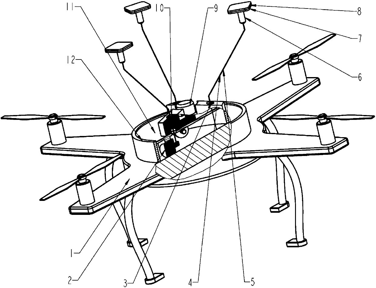
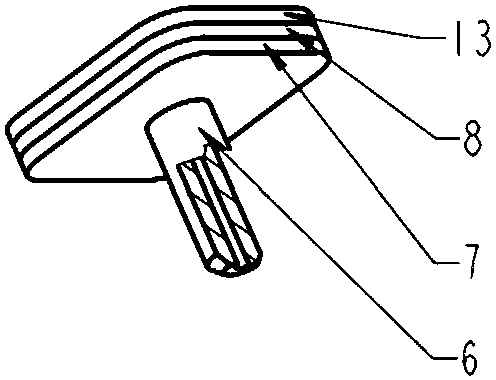
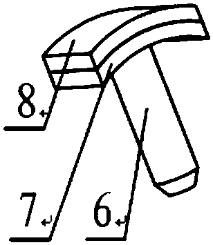
[0024] like figure 1 , the present embodiment includes a multi-rotor drone 1, a stepper motor 2, a launch chamber 3, a hollow rope 4, a wire 5, a launch rod 6, a piezoelectric sheet 7, an imitation gecko foot 8, a pan-tilt camera 9, and a launch coil 10 1. Install the flat panel 11 and the installation box 12, the installation box 12 is divided into upper and lower layers by the installation flat panel 11, and three emission chambers 3 are evenly distributed on the upper side of the installation flat panel, and one group of emission coils 10 is fixed in each emission cavity 3, There is a pan-tilt camera 9 in the center; three stepper motors 2 are evenly distributed in the middle of the lower side of the installation plate, and the shaft of the stepper motor 2 is wound with a hollow rope 4, which is connected to the bottom end of the launch rod 6 through the launch cavity 3 , and connected to the piezoelectric sheet 7 through the launch rod 6, the launch rod 6 is hollow. The h...

Embodiment 2

[0033] The difference between embodiment 2 and embodiment 1 is that embodiment 2 replaces the hollow rope with the common mechanical arm structure in the prior art. The mechanical arm can adopt a multi-bending structure, and a piezoelectric The piezoelectric sheet is provided with imitation gecko feet, and the surface of the imitation gecko feet is provided with bristle arrays. The control device controls the lifting of the mechanical arm structure, and the piezoelectric sheet controls the imitation gecko feet. The principle of the control device is the same as that of Embodiment 1.


PUM


Abstract

The invention provides an energy-saving multi-rotor UAV device based on bionic suspension, which includes a UAV device body, and the UAV device body is provided with imitation gecko feet that can be connected to objects; Under the control of the device body or an external remote control device, it can be connected or separated from external objects. The rope is a hollow rope, and the UAV device body is provided with a mounting plate, and the mounting plate is provided with more than one launching chamber, and a transmitting coil is fixed in the launching chamber, and the lower end of the launching chamber is provided with a There is a stepping motor, the stepping motor is connected to the hollow rope, the other end of the hollow rope is connected to the piezoelectric sheet, the lower end of the piezoelectric sheet is provided with a launch rod adapted to the firing chamber, and the upper end of the piezoelectric sheet is provided with a gecko imitation feet, the stepper motor includes a shaft to which a hollow cord is wound.

Description

technical field [0001] The invention relates to the field of unmanned aerial vehicles, in particular to an energy-saving multi-rotor unmanned aerial vehicle based on bionic suspension. Background technique [0002] At present, unmanned aerial vehicles have been widely used in reconnaissance, monitoring, photography, relay and other flying mobile platforms and tools, and carry out aerial fixed-point inspections and other tasks. When multi-rotor drones perform tasks such as fixed-point inspections, photography, and monitoring, they usually need to reach the destination in advance, wait at the destination, or stop on the way to perform tasks. The time for performing tasks is limited by the battery power of the drone. How to Improving the working hours of drones so that they can complete long-term monitoring, wait for tasks and return under limited power is a current problem. [0003] At present, some long-endurance multi-rotor UAVs mainly use tethered power supply, and the UAV...

Claims


Application Information

Patent Timeline
Patent Type & Authority Patents(China)
IPC IPC(8): B64C27/08B64D47/00
CPCB64C27/08B64D47/00B64U10/10
Inventor 周远远杨青龙王腾戚宝运杨燕杨波
Owner THE 28TH RES INST OF CHINA ELECTRONICS TECH GROUP CORP
Why Eureka
Try Eureka