
Single lifting distributing platform for tubular workpiece

A technology for distributing tables and workpieces, applied in the direction of conveyor objects, conveyors, transportation and packaging, etc., can solve the problems of difficult clamping and processing of tubular workpieces, increase the equipment footprint, and cannot be stacked to achieve production Low cost, simple and compact structure, and the effect of reducing production costs

Inactive Publication Date: 2016-08-31
ZHEJIANG UNIV OF TECH
View PDF8 Cites 4 Cited by
  • Summary
  • Abstract
  • Description
  • Claims
  • Application Information

AI Technical Summary

Problems solved by technology

[0002] Tubular workpieces are tube-shaped workpieces, and the transportation of tubular workpieces is usually carried out by conveyor belts; however, in the actual production and processing process, it is usually necessary to process both ends of the tubular workpieces one by one; while the traditional conveyor belt is carrying out tubular workpieces During transportation, the tubular workpieces are connected one by one, it is difficult to clamp and process the tubular workpieces one by one
[0003] At the same time, in the process of using the conveyor belt to process tubular workpieces, the floor space of the equipment will be greatly increased. The tubular workpieces can only be arranged side by side on the surface of the conveyor belt and cannot be piled up. Therefore, manual loading of the tubular workpieces is still required. The workpiece is placed on the conveyor belt, which also increases labor costs

Method used


Image

  • Single lifting distributing platform for tubular workpiece
  • Single lifting distributing platform for tubular workpiece
  • Single lifting distributing platform for tubular workpiece

Examples


Embodiment Construction

[0022] The present invention will be further described below in conjunction with accompanying drawing:

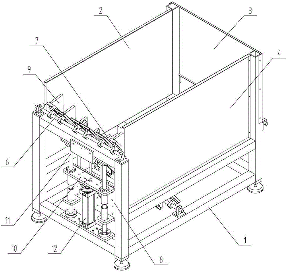
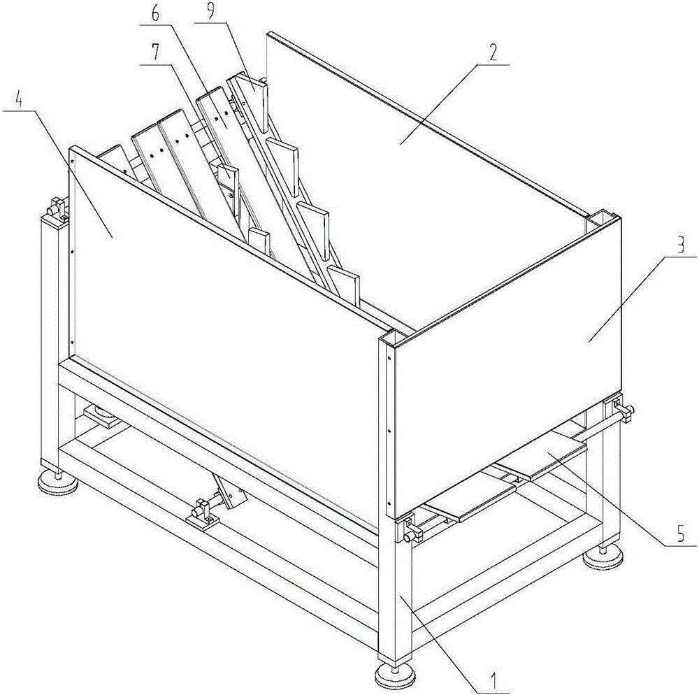
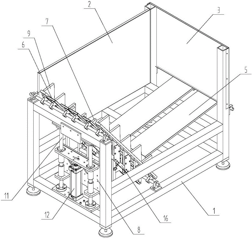
[0023] Such as Figure 1~6 As shown, a single lifting and distributing platform for a tubular workpiece includes a frame 1, a left baffle 2, a right baffle 3, a rear baffle 4, a storage plate 5, a lifting panel 6, a jacking plate 7, and a jacking and fixing Plate 8, slide block 10, linear guide rail 11 and linear cylinder 12, frame 1 is a frame made of aluminum profiles, and the bottom of frame 1 is provided with four supporting feet.

[0024] The material storage plate 5 is obliquely arranged on the bottom of the frame 1, the material storage plate 5 is inclined towards the lifting panel 6 direction and the inclination angle between the material storage plate 5 and the horizontal plane is 5-15 °, the material storage plate 5 can be a The whole straight board can also be a plurality of strip-shaped straight boards arranged in parallel, and the tubular workpiece can roll al...


PUM


Abstract

The invention discloses a single lifting distributing platform for a tubular workpiece. The single lifting distributing platform comprises a rack, a left baffle plate, a right baffle plate, a rear baffle plate, a material storing plate, a lifting panel, a propping plate, a propping fixing plate, a slide block, linear guide rails and a linear cylinder, wherein the material storing plate, the left baffle plate, the right baffle plate, the rear baffle plate and the lifting plane form a box body for storing the tubular workpiece; a plurality of lifting step-shaped plates are arranged on the lifting plane, and each lifting step-shaped plate is provided with a corresponding propping plate row; all propping plates are fixed to the propping fixing plate which is fixedly connected with the slide block; two linear guide rails are arranged on the rack; the slide block sleeves the two linear guide rails; the linear cylinder can move to drive the slide block to vertically move along the linear guide rails so as to control the propping plate to lift up and down. The single lifting distributing platform for the tubular workpiece is simple in structure; the tubular workpiece can be individually lifted and conveyed, and the whole process is automatically carried out and free of manual control, so that the convenience of processing is greatly improved, and the tubular workpiece conveying efficiency and stability can be improved.

Description

technical field [0001] The invention relates to a pipe fitting conveying device, more specifically, to a single lifting and distributing table for tubular workpieces. Background technique [0002] Tubular workpieces are tube-shaped workpieces, and the transportation of tubular workpieces is usually carried out by conveyor belts; however, in the actual production and processing process, it is usually necessary to process both ends of the tubular workpieces one by one; while the traditional conveyor belt is carrying out tubular workpieces During transportation, the tubular workpieces are connected one by one, and it is difficult to clamp and process the tubular workpieces one by one. [0003] At the same time, in the process of using the conveyor belt to process tubular workpieces, the floor space of the equipment will be greatly increased. The tubular workpieces can only be arranged side by side on the surface of the conveyor belt and cannot be piled up. Therefore, manual loa...

Claims


Application Information

Patent Timeline
Patent Type & Authority Applications(China)
IPC IPC(8): B65G47/14
CPCB65G47/1471B65G2201/0276
Inventor 孙建辉张锐袁智敏
Owner ZHEJIANG UNIV OF TECH
Learn More