Spiral vertical lifting mechanism

A vertical lifting and spiral technology, which is applied in elevators, lifting equipment in mines, elevators in buildings, etc., can solve the problems of slow lifting speed, small diameter of jacking columns, and low work efficiency, so as to improve the service life , increase the support area, improve the effect of efficiency

Inactive Publication Date: 2016-08-31
刘翔
View PDF6 Cites 8 Cited by
  • Summary
  • Abstract
  • Description
  • Claims
  • Application Information

AI Technical Summary

Problems solved by technology

[0004] However, the diameter of the jacking column of the above-mentioned cordless vertical lifting mechanism is small, and under the same thread lead angle, the lead of the thread is small, resulting in a slow lifting speed and low work efficiency.

Method used


Image

  • Spiral vertical lifting mechanism
  • Spiral vertical lifting mechanism
  • Spiral vertical lifting mechanism

Examples


Embodiment 1

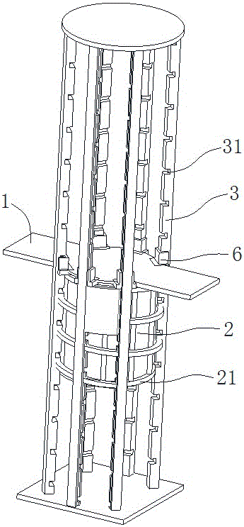
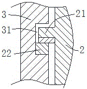
[0031] Embodiment 1: as Figure 1~Figure 3As shown, a spiral vertical lifting mechanism includes a horizontally arranged load-bearing plate 1, a lifting column 2 vertically installed at the bottom of the load-bearing plate 1 and capable of rotating around its own axis, and adjacent to the lifting column 2 along the circumferential direction. Several vertical columns 3 are arranged, and a driving device arranged between the bearing plate 1 and the lifting column 2 for driving the rotation of the lifting column 2; the circumferential surface of the lifting column 2 There is a helical edge 21 protrudingly arranged around the jacking column 2, the maximum diameter of the helical edge 21 is larger than the diameter of the inner common tangent circle of the several columns 3, and the minimum diameter of the helical edge 21 is smaller than the several The diameter of the outer common tangent circle of the column 3; the side of the column 3 facing the lifting column 2 has guide groove...

Embodiment 2

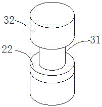
[0047] Embodiment 2: as Figure 4 As shown, the difference from Embodiment 1 is that the upward facing surface of the guide groove 31 also has a concave spherical hole, and a rolling ball is embedded in the spherical hole, and the upper end of the ball is exposed. on the surface.

[0048] In this way, since the upper end of the ball exposes the upward surface of the guide groove, the lower surface of the helical edge fitted in the guide groove is in contact with the ball. Rolling in the spherical hole, so that the sliding friction between the helical edge and the guide groove is changed into rolling friction, which is beneficial to improve the flexibility of movement, reduce wear and improve the service life.

[0049] During implementation, the lower surface of the helical rib 21 has a groove arranged along the helical rib, the cross section of the groove is arc-shaped, and the radius of the arc is consistent with the radius of the ball; the depth of the groove is consistent ...


PUM


Abstract

The invention discloses a spiral vertical lifting mechanism. The spiral vertical lifting mechanism comprises a bearing plate, lifting posts, upright posts and a driving device, wherein the lifting posts are vertically installed at the bottom of the bearing plate, the upright posts are circumferentially arranged next to the lifting posts, and the driving device is arranged between the bearing plate and the lifting posts and is used for driving the lifting posts to rotate; spiral ridges which are spirally coiled upwards around the lifting posts in a protruded mode are formed on the circumferential surfaces of the lifting posts, and the large diameter of the spiral ridges is greater than the diameter of a common tangent circle of a plurality of upright posts; guide grooves which are formed at equal intervals along the length direction are formed in one side, which faces towards the lifting posts, of each upright post, the guide grooves are formed in a penetrating mode along the direction of the spiral ridges, and the distance between the two adjacent guide grooves is the same as the lead of the spiral ridges; the guide grooves in the plurality of upright posts are arranged in a spiral shape consistent with the spiral ridges along the circumferential direction of the lifting posts; the spiral ridges are matched and arranged in the guide grooves of the plurality of upright posts and can be guided to lift by the guide grooves by virtue of self rotation. The spiral vertical lifting mechanism has the advantages of high lifting speed, light weight, low noise, capability of lubrication, high use safety, long service life and the like.

Description

technical field [0001] The invention relates to a lifting mechanism, in particular to a spiral vertical lifting mechanism. Background technique [0002] The vertical lifting mechanism is a kind of equipment for lifting goods or people to a high place, which is widely used in mines and construction sites. In the existing lifting mechanism, the structural form of steel wire rope and hoist is usually used for lifting. Existing patents all adopt the above-mentioned structural form, which has the characteristics of convenient lifting. However, in the lifting mode of this structural form, in the process of lifting, when there is a sudden accident that the steel wire rope breaks, the lifting object may fall from a high altitude, thereby endangering the safety of personnel and goods. [0003] For this reason, the inventor once designed a kind of cordless vertical lifting mechanism, including several uniformly vertically arranged cylindrical bodies, jacking columns screwed in the in...

Claims


Application Information

Patent Timeline
Patent Type & Authority Applications(China)
IPC IPC(8): B66B9/00B66B7/02B66B7/12B66B17/02B66B11/04B66B15/08
CPCB66B7/02B66B7/1246B66B9/00B66B11/043B66B15/08B66B17/02
Inventor 刘纯明刘翔
Owner 刘翔
Why Eureka
Try Eureka