Ultraviolet lamp tube fixing device in marine ballast water system

A fixed device, ballast water technology, applied in natural water treatment, water/sewage treatment, illumination water/sewage treatment, etc. Tight fit and better fixation effect

Active Publication Date: 2016-08-31
WEIHAI COSCO SHIPBUILDING TECH CO LTD
View PDF4 Cites 2 Cited by
  • Summary
  • Abstract
  • Description
  • Claims
  • Application Information

AI Technical Summary

Problems solved by technology

Existing this ultraviolet lamp fixing device has the following disadvantages: 1. There is a radial fit gap between the radial positioning plate and the inner wall of the quartz sleeve. Large impact force may easily cause fracture and damage to the quartz sleeve and ultraviolet lamp tube
2. There is an axial installation gap between the radial positioning plate and the step of the installation head of the ultraviolet lamp tube, and the axial installation gap will increase with the prolongation of the use time. When the hull tilts and sways, the lamp tube will move axially If the radial positioning plate hits the lamp tube, the service life will be shortened or even broken.
3. The radial positioning plate seals the installation head at the end of the ultraviolet lamp relatively in a small space, so its cooling is limited. When working, the high temperature generated by the installation head at the end of the ultraviolet lamp is not released in time, which will shorten the Its service life even melts the metal mounting head

Method used


Image

  • Ultraviolet lamp tube fixing device in marine ballast water system
  • Ultraviolet lamp tube fixing device in marine ballast water system
  • Ultraviolet lamp tube fixing device in marine ballast water system

Examples


Embodiment Construction

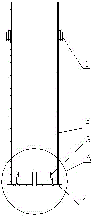
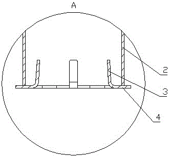
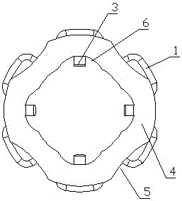
[0019] Such as Figure 1-5 The ultraviolet lamp fixing device in the marine ballast water system shown is provided with a support sleeve 2, and an elastic foot 1 is provided on the outer wall of the support sleeve 2, from which Figure 4 , Figure 6 It can be seen from the figure that two groups of elastic legs are arranged in the axial direction of the support sleeve, each group has three elastic legs, and the three elastic legs of each group are arranged on the support sleeve evenly in the circumferential direction; or on the outer wall of the support sleeve. Fabric elastic feet; from Figure 5 It can be seen from the figure that the elastic leg is in the shape of a square block, the outer surface of the elastic leg is an arc surface that closely fits with the inner wall of the quartz sleeve, the inner surface of the elastic leg is an arc surface that is closely matched with the outer wall of the support sleeve, and the inner surface of the elastic leg is Closely fixed on ...


PUM


Abstract

The invention provides an ultraviolet lamp tube fixing device in a marine ballast water system. The ultraviolet lamp tube fixing device is provided with a supporting sleeve. Elastic supporting legs are arranged on the outer wall of the supporting sleeve. A lamp tube installing plate is arranged at one end of the supporting sleeve. An installing hole is formed in the middle of the lamp tube installing plate. At least three strip-shaped fixing elastic pieces are uniformly distributed on the inner wall of the installing hole in the peripheral direction. One end of each fixing elastic piece is fixedly connected to the inner wall of the installing hole, and the other end of each fixing elastic piece is bent towards the interior of the supporting sleeve. The lamp tube installing plate is round. Ventilating and heat dissipating notches are uniformly distributed in the periphery of the lamp tube installing plate. The installing hole in the middle of the lamp tube installing plate is a round hole. Arc-shaped installing grooves are uniformly distributed in the inner wall of the installing hole in the circumferential direction. The fixing elastic pieces are installed in the installing grooves. The included angle of 2-10 degrees is formed between the part, bent into the supporting sleeve, of each fixing elastic piece and the axis of the installing hole. The ultraviolet lamp tube fixing device is simple in structure, low in cost, easy and convenient to install and good in damping and buffering effect, and an ultraviolet lamp tube can not be damped easily and is long in service life.

Description

technical field [0001] The invention relates to a bacteria killing device in a ship's ballast water system, in detail, it is a ship's ballast with simple structure, low cost, simple and convenient installation, good shock absorption and buffering effect, undamaged ultraviolet lamp tube and long service life UV lamp fixtures in water systems. Background technique [0002] We know that the marine ballast water system used in UV inactivation technology belongs to the physical killing technology. Because of its characteristics of no environmental pollution, no need to use additional consumables, and compact structure, it occupies a large market share in the ballast water field. The core component of ultraviolet inactivation is the ultraviolet lamp in the ultraviolet reactor. Because the interior of the ultraviolet reactor is full of seawater when it is working, a quartz sleeve is installed outside the ultraviolet lamp to isolate the seawater. The supporting components of the ul...

Claims


Application Information

Patent Timeline
Patent Type & Authority Applications(China)
IPC IPC(8): C02F1/32
CPCC02F1/325C02F2201/322C02F2103/008
Inventor 韩德民王晋王泽华谷斌李升杰
Owner WEIHAI COSCO SHIPBUILDING TECH CO LTD
Why Eureka
Try Eureka