Transverse gateway movement structure

A core and horizontal technology, applied in the field of horizontal barrier core structure, can solve the problems of unreasonable deceleration structure of the reducer, difficult to guarantee the working performance, complex and cumbersome overall structure, etc., to achieve increased space utilization and fast transmission response , cost reduction effect

Inactive Publication Date: 2016-08-31
GUANGDONG ANKUAI INTELLIGENT TECH CO LTD
View PDF7 Cites 1 Cited by
  • Summary
  • Abstract
  • Description
  • Claims
  • Application Information

AI Technical Summary

Problems solved by technology

First, the overall structure is relatively complicated and cumbersome, occupying the space inside the chassis; and the motor of the movement transmission mechanism is vertically arranged under the reducer, which is easy to cause oil leakage, because the output shaft of the motor penetrates from the bottom of the reducer After running for a long time, the fit must not be tight enough, and the oil will seep out from the gap, affecting the operation and leaving a safety hazard
Second, the deceleration structure of the reducer itself is unreasonable, and a transfer device must be installed to connect with the motor, and a multi-stage gear set is used for deceleration, which has low efficiency, high energy consumption, and high noise, making it difficult to guarantee the working performance
Third, in the event of a power failure, the door of the cabinet must be opened to raise the gate lever manually, which is complicated to operate
All in all, there are still many unreasonable places in the structure of the traditional barrier gate mechanism, and a new technical solution needs to be proposed to avoid the above-mentioned shortcomings

Method used


Image

  • Transverse gateway movement structure
  • Transverse gateway movement structure

Examples


Embodiment Construction

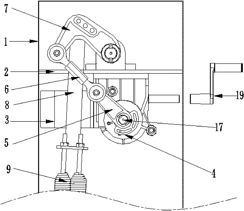
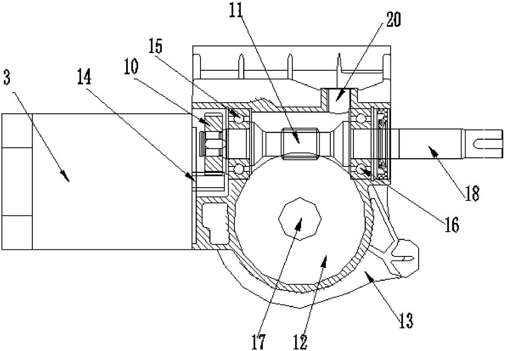
[0018] see Figures 1 to 2 , the movement structure of the horizontal barrier gate provided in this embodiment includes a chassis 1, a movement transmission mechanism and a connecting rod transmission mechanism, and the movement movement mechanism and the connecting rod transmission mechanism are arranged in the chassis 1, wherein the machine The core transmission mechanism is fixedly arranged through the movement fixed plate 2, and one end of the connecting rod transmission mechanism is connected with the output end of the movement transmission mechanism, and the other end is connected with the gate bar; the movement movement mechanism of the barrier gate includes a motor 3 and the reducer 4, the motor 3 is arranged laterally on the side of the reducer 4.

[0019] Specifically, the connecting rod transmission mechanism includes a first straight connecting rod 5, a second straight connecting rod 6 and a third L-shaped connecting rod 7 which are sequentially hinged, wherein the...


PUM


Abstract

The invention discloses a transverse gateway movement structure which comprises a machine case, a movement driving mechanism and a connecting rod driving mechanism. The movement driving mechanism and the connecting rod driving mechanism are arranged in the machine case, the movement driving mechanism is fixedly arranged through a movement fixing plate, one end of the connecting rod driving mechanism is connected with the output end of the movement driving mechanism, and the other end of the connecting rod driving mechanism is connected with a gateway rod. The transverse gateway movement structure is characterized in that the gateway movement driving mechanism comprises an electric motor and a speed reducer, wherein the electric motor is transversely arranged on the side of the speed reducer. The transverse gateway movement structure is scientific and reasonable, the overall size can be decreased, the occupied space in the machine case is smaller, and the transverse gateway movement structure is convenient to install and fix, so that the utilization of the space in the machine case is maximized. In addition, the transverse gateway movement structure can also avoid an oil leakage phenomenon of the speed reducer and is high in efficiency, low energy consumption and small in noise.

Description

technical field [0001] The invention relates to a core structure of a barrier gate, in particular to a core structure of a horizontal barrier gate. Background technique [0002] The traditional structure of the gate movement has the following deficiencies. First, the overall structure is relatively complicated and cumbersome, occupying the space inside the chassis; and the motor of the movement transmission mechanism is vertically arranged under the reducer, which is easy to cause oil leakage, because the output shaft of the motor penetrates from the bottom of the reducer After running for a long time, the fit must not be tight enough, and the oil will seep out from the gap, affecting the operation and leaving a safety hazard. Second, the deceleration structure of the reducer itself is unreasonable. A relay device must be installed to connect with the motor, and a multi-stage gear set is used for deceleration. The efficiency is low, the energy consumption is high, the noise...

Claims


Application Information

Patent Timeline
Patent Type & Authority Applications(China)
IPC IPC(8): E01F13/04
CPCE01F13/04
Inventor 肖勇善
Owner GUANGDONG ANKUAI INTELLIGENT TECH CO LTD
Why Eureka
Try Eureka