Mining pumping and spraying integrated vehicle

An integrated, mine-used technology, applied in road cleaning, construction, cleaning methods, etc., can solve the problems of high cost of auxiliary materials, high pump power, high cost, etc., to reduce secondary treatment costs, fast water treatment speed, and engineering volume small effect

Active Publication Date: 2016-08-31
CHINA SHENHUA ENERGY CO LTD +1
View PDF8 Cites 1 Cited by
  • Summary
  • Abstract
  • Description
  • Claims
  • Application Information

AI Technical Summary

Problems solved by technology

[0006] 1. The amount of auxiliary engineering for erecting water pump circuits and draining pipelines is large;
[0007] 2. Laying the water pump circuit and draining the pipeline requires a lot of cables and pipes, and the cost of purchasing auxiliary materials is relatively high;
[0008] 3. The occupation of the transportation road by the drainage pipeline will hinder the normal use of the mine transportation system;
[0009] 4. The use of water pumps for pumping and drainage requires a large amount of construction work and high power pumps. It is necessary to gather all the water from the working face for pumping and drainage at one time, resulting in ditches everywhere on the working face and poor engineering quality;
[0010] 5. After the effluent from the working face of the stope is pumped and drained to the sump of the stope by the water pump drainage pipeline, secondary treatment is required to pump the effluent from the working face to the ground water filling station, and then sprinkle water and dust by ordinary sprinklers, the process is cumbersome ,higher cost

Method used


Image

  • Mining pumping and spraying integrated vehicle
  • Mining pumping and spraying integrated vehicle
  • Mining pumping and spraying integrated vehicle

Examples


Embodiment Construction

[0033] The technical solutions of the present invention will be described in detail below in conjunction with the accompanying drawings and specific embodiments.

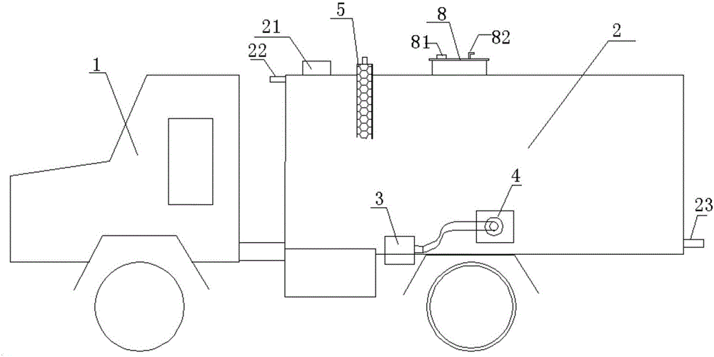
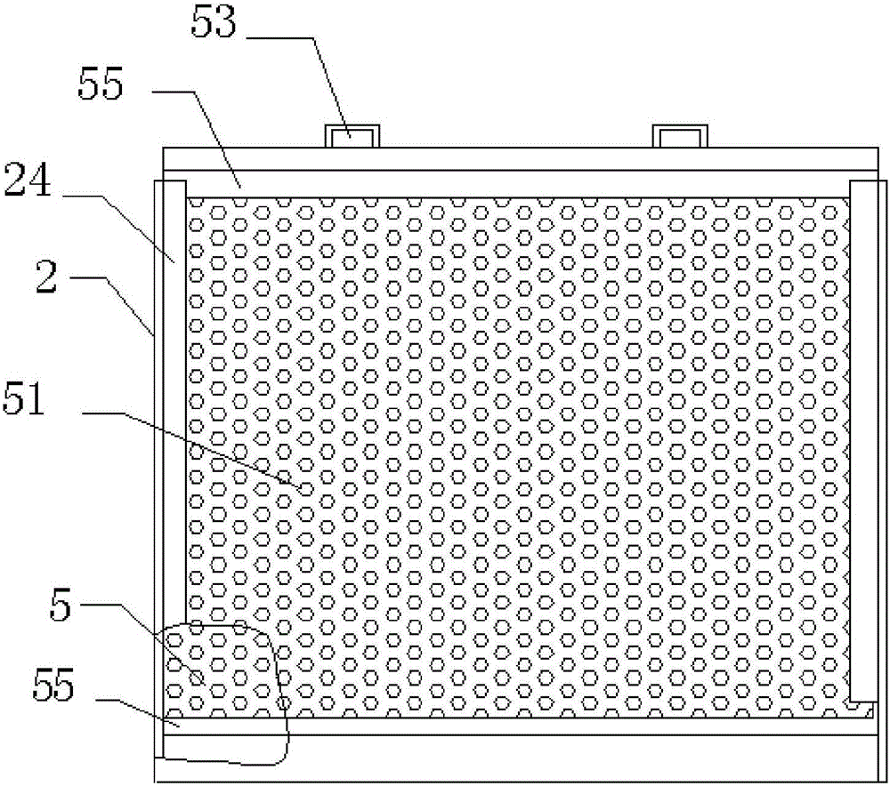
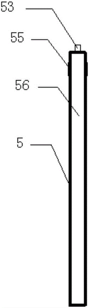
[0034] figure 1 Shown is the overall structure of the integrated mine pumping and sprinkler vehicle according to the embodiment of the present invention, which includes: a car body 1, a water tank 2, a filter plate 5 and a pumping and sprinkler device. Wherein, the water tank 2 is installed on the car body 1, and the filter plate 5 is installed inside the water tank 2, figure 1 shows schematically the upper half of the filter plate 5, the entire filter plate 5 divides the internal space of the water tank 2 into a muddy water chamber and a clean water chamber, figure 1 The left side of the middle filter plate 5 is a muddy water chamber, and the right side is a clean water chamber. The water inlet 21 of the water tank 2 is located at the top of the muddy water chamber. The extraction unit is located under the solut...


PUM


Abstract

The invention discloses a mining pumping and spraying integrated vehicle. The mining pumping and spraying integrated vehicle includes a vehicle body, a water tank, a filtering plate and a pumping and spraying device; the water tank is arranged on the vehicle body; the filtering plate is arranged in the water tank; the inner space of the water tank is divided into a muddy water chamber and a clean water chamber by the filtering plate; a water inlet of the water tank is formed in the top of the muddy water chamber; the pumping and spraying device is positioned under the clean water chamber; the pumping and spraying device includes a water pump, a water intake pipe, a floating platform and a nozzle, wherein the water pump is arranged on the bottom of the clean water chamber, the water pump is connected to the floating platform through the water intake pipe, and the floating platform includes a suspensible material for allowing an opening of the water intake pipe to be in a preset depth under water surface of the clean water chamber; the water pump pumps water in the clean water chamber, and then water is sprayed through the nozzle; the water pump is connected to the water inlet through a pipeline; and a sediment deposition pool is arranged on the bottom of the muddy water chamber. The mining pumping and spraying integrated vehicle can pump water on a stope working face into the water tank and spray a road with water to remove dust; the process is simple; and the cost is low.

Description

technical field [0001] The invention relates to the technical field of refitted mine vehicles, in particular to a mine pumping and sprinkler integrated vehicle. Background technique [0002] In open-pit mining, affected by geological and hydrological conditions, aquifers are often encountered in the formation. The water outlet of the aquifer has the characteristics of many water outlet points and regionalization. Water seepage from the aquifer often results in a large amount of standing water at the working face. Soaked in water, the rock and soil on the working face are soft, which can easily cause shovel sinking and car sinking accidents. [0003] At present, the solution to water discharge from the working face is mainly to collect the water seeping from the working face through the ditch, and then use the water pump pipeline to pump it into a fixed sump in the stope. The power consumption of large equipment in the open pit mine is 6KV, while the power consumption of o...

Claims


Application Information

Patent Timeline
IPC IPC(8): E01H1/00
CPCE01H1/00
Inventor 佘长超
Owner CHINA SHENHUA ENERGY CO LTD
Why Eureka
Try Eureka