Proportional type proportional pressure reducing valve

A proportional decompression valve, proportional technology, applied in safety valves, balance valves, valve devices, etc., can solve the problems of comparative control of output displacement and inability to control output force, etc., to achieve changing response speed, good hydraulic force elimination, and elimination Effect of Range Loss

Active Publication Date: 2016-08-31
HARBIN INST OF TECH
View PDF5 Cites 6 Cited by
  • Summary
  • Abstract
  • Description
  • Claims
  • Application Information

AI Technical Summary

Problems solved by technology

However, the piezoelectric actuator can only output a small displacement proportional to the control voltage, which cannot be compared with the hydrau

Method used


Image

  • Proportional type proportional pressure reducing valve
  • Proportional type proportional pressure reducing valve
  • Proportional type proportional pressure reducing valve

Examples


specific Embodiment approach 1

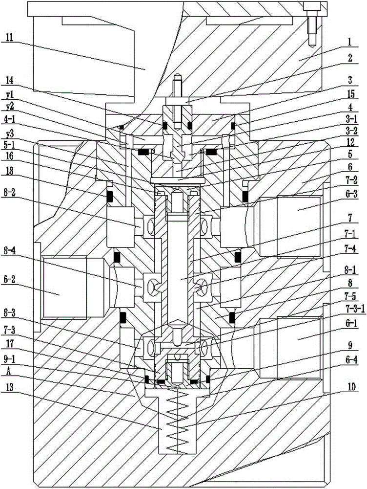
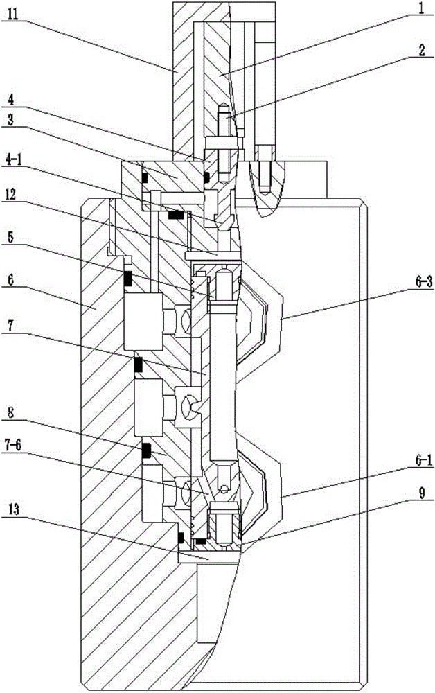
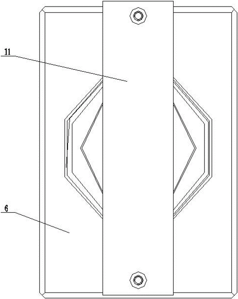
[0052] Specific implementation mode one: as Figure 1 to Figure 4 As shown, a proportional proportional pressure reducing valve includes a piezoelectric actuator 1, a pilot valve, a main valve, a valve block 6 and a mounting bracket 11; the pilot valve includes a pilot valve seat 3, a pilot valve core 4 and Pilot valve oil supply 5; the middle part of the pilot valve seat 3 is provided with a coaxial and connected center hole 3-1 and a seat hole 3-2 from top to bottom, and the main valve includes a main valve core 7 and a valve body 8 , main spool damper 9 and zero adjustment spring 10;

[0053] The piezoelectric actuator 1 is connected to the upper end surface of the valve body 8 through the mounting bracket 11, and the lower end surface of the piezoelectric actuator 1 is connected to the upper end surface of the pilot valve core 4 (via the connecting bolt 2) (the piezoelectric actuator The actuator 1 directly acts on the pilot spool 4 to cause displacement of the pilot spoo...

specific Embodiment approach 2

[0059] Specific implementation mode two: as figure 1 As shown, a proportional proportional pressure reducing valve described in Embodiment 1, the outer cylindrical surface (also called the guide section) on the upper part of the pilot valve core 4 is processed with a sealing ring groove for preventing oil leakage One, the sealing ring one 14 is arranged in the sealing ring groove one.

specific Embodiment approach 3

[0060] Specific implementation mode three: as figure 1 As shown, a proportional proportional pressure reducing valve described in the first specific embodiment, the outer peripheral surface of the pilot valve seat 3 is processed with a sealing ring groove 2 for preventing oil leakage, and the sealing ring A sealing ring 2 15 is arranged in the groove 2.


PUM


Abstract

The invention discloses a proportional type proportional pressure reducing valve and belongs to the technical field of pressure reducing valves. A piezoelectric actuator is connected with a pilot valve element. The pilot valve element is matched with a pilot valve seat to form a pilot valve port. A main valve upper cavity is formed between a pilot valve oil supply device and the pilot valve seat. A main valve element damper is arranged in a main valve element. A shoulder of an upper section of the main valve element and the edge of a sinking and cutting groove in the upper portion of a valve body are matched to form an oil draining valve port, a shoulder of a lower section of the main valve element is matched with the edge of a sinking and cutting groove in the lower portion of the valve body to form an oil inlet valve port, and a shoulder of a middle section of the main valve element corresponds to a sinking and cutting groove in the middle portion of the valve body to form an output and flow guide part. The valve body is arranged in a valve block. An oil inlet and an oil draining port of the valve block communicate with the oil inlet valve port and the oil draining valve port correspondingly. A load opening of the valve block communicates with the sinking and cutting groove formed in the middle portion of the valve body, and a zero adjustment spring is arranged in a main valve lower cavity. Partial pressure of the pilot valve port and a throttling hole of the pilot valve oil supply device is used as a main valve element instruction, and the zero adjustment spring is used for expanding the pressure adjusting range. By means of the proportional type proportional pressure reducing valve, the output pressure of the valve and the input pressure of the valve can change proportionally.

Description

technical field [0001] The invention relates to an electro-hydraulic proportional pressure reducing valve. The utility model belongs to the technical field of pressure reducing valves. Background technique [0002] The existing proportional pressure reducing valve generally adopts a proportional electromagnet as a control element, and the output pressure is a fixed value, and the output pressure is controlled by adjusting the proportional electromagnet. In these valves, the proportional electromagnet generates a force proportional to the control signal to act on the valve core, and the output hydraulic pressure acts on the other end of the valve core. When the electromagnetic force and hydraulic pressure are balanced, the proportional pressure reducing valve reaches a balanced state. Therefore, the output pressure is proportional to the electromagnetic force, so the output hydraulic pressure can be controlled by the electromagnetic force. [0003] Due to the quick response...

Claims


Application Information

Patent Timeline
IPC IPC(8): F16K17/32
CPCF16K17/32
Inventor 杨庆俊汪俊龙贾新颖刘志恒吕庆军熊庆辉
Owner HARBIN INST OF TECH
Why Eureka
Try Eureka