Automatic efficient drawing force testing device

A testing device, high-efficiency pulling technology, applied to measuring devices, using stable tension/pressure to test material strength, instruments, etc., can solve the problems of consuming staff, complicated testing, inflexible operation, etc., and achieve simple structure of the device, The effect of improving test efficiency and ensuring accuracy

Inactive Publication Date: 2016-08-31
SUZHOU JUNFA PRECISION MACHINERY
View PDF6 Cites 3 Cited by
  • Summary
  • Abstract
  • Description
  • Claims
  • Application Information

AI Technical Summary

Problems solved by technology

[0002] Some existing plastic products are usually designed with a boss column, and the pull-out force that the boss column can withstand is an important indicator to ensure product quality. , and then another worker uses the hook on the tension meter to reach the boss column of the column product, and then pulls it up until the boss column is broken. This test method consumes a lot of physical strength of the staff, and the test is complicated, and this This manual test method has large errors and the data is not accurate enough
[0003] Moreover, the position of the tension gauge of the existing pull-out force testing device is fixed, and it is very inflexible to operate
[0004] At the same time, the existing pull-out force testing device usually presses the plastic product manually to prevent the plastic product from being pulled up together during the pull-out process, which will affect the test results. This method consumes more manpower, is not automatic enough, and affects Test efficiency

Method used


Image

  • Automatic efficient drawing force testing device
  • Automatic efficient drawing force testing device
  • Automatic efficient drawing force testing device

Examples


Embodiment

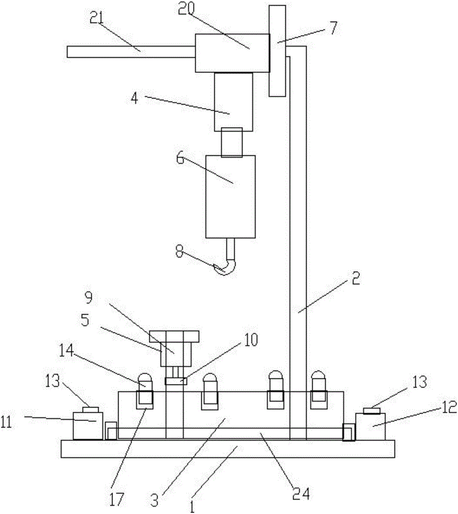
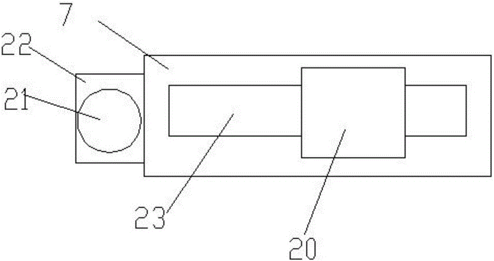
[0028] Embodiment:. An automatic high-efficiency pull-out force testing device, comprising workbench 1, fixed rod 2, beam 7, slide block 20, positioning block 3, lifting cylinder 4, compression cylinder 5 and tension gauge 6, described fixed The rod is vertically fixed on the workbench, the fixed rod is in an inverted L-shape, the beam moves left and right and is connected to the L-shaped straight part of the fixed rod, and the slider slides back and forth and is horizontally connected to the beam side of

[0029] The lifting cylinder is vertically fixed on the lower end of the slider, the tension gauge is vertically fixed on the head of the lifting cylinder, the lower end of the tension gauge is fixedly connected with a hook 8, and the positioning block is freely placed on the on said workbench;

[0030] A ball screw 24 is horizontally installed on the workbench, and the left and right movement of the ball screw is provided with a ball bearing 25, and also includes a support...


PUM


Abstract

The invention discloses an automatic efficient drawing force testing device, which comprises a workbench, a fixed rod, a cross beam, a sliding block, a locating block, a lifting air cylinder, a compaction air cylinder and a tensiometer. The fixed rod is vertically fixed on the workbench and is in the shape of inverted L. The cross beam moves to the left and right and is connected to a horizontal part of the L shaped fixed rod. The sliding block slides back and forth and is horizontally connected to one side of the cross beam. The lifting air cylinder is vertically fixed at the lower end of the sliding block, the tensiometer is vertically fixed at the head of the lifting air cylinder, the lower end of the tensiometer is fixedly connected to a hook, the workbench is horizontally equipped with a ball screw, and a ball bearing moving left and right is sleeved on the ball screw. The device also includes a support frame. The support frame is vertically fixed on the ball bearing, the compaction air cylinder moves up and down and slides back and forth to be connected to the support frame, the compaction air cylinder is disposed vertically, and a pressing block is fixed at the head of the compaction air cylinder.

Description

technical field [0001] The invention relates to a pull-out force test device, in particular to an automatic high-efficiency pull-out force test device. Background technique [0002] Some existing plastic products are usually designed with a boss column, and the pull-out force that the boss column can withstand is an important indicator to ensure product quality. , and then another worker uses the hook on the tension meter to reach the boss column of the column product, and then pulls it up until the boss column is broken. This test method consumes a lot of physical strength of the staff, and the test is complicated, and this This manual test method has large errors and the data is not accurate enough. [0003] Moreover, the position of the tension gauge of the existing pull-out force testing device is fixed, and the operation is very inflexible. [0004] At the same time, the existing pull-out force testing device usually presses the plastic product manually to prevent the...

Claims


Application Information

Patent Timeline
Patent Type & Authority Applications(China)
IPC IPC(8): G01N3/10G01N3/04
CPCG01N3/10G01N3/04
Inventor 薛桂芬陆佳俊陆雪松
Owner SUZHOU JUNFA PRECISION MACHINERY
Why Eureka
Try Eureka