
Counterweight support and motor applying the support

A technology of counterweight and counterweight block, which is applied to electrical components, electromechanical devices, electric components, etc., can solve the problems that the rotor parts are not beautiful in appearance, increase the difficulty and cost, and are unfavorable for later replacement, and achieve simple structure, convenient and reliable use. , the effect of beautiful appearance

Inactive Publication Date: 2016-08-31
江阴市澳盛动力设备有限公司
View PDF10 Cites 2 Cited by
  • Summary
  • Abstract
  • Description
  • Claims
  • Application Information

AI Technical Summary

Problems solved by technology

[0003] The conventional correction method is: de-weight or increase the weight of the motor rotor; because the de-weight will affect the magnetic flux of the electronic rotor, the method of adding weight is generally used nowadays; the usual method of adding weight is to add a nut to the pad, or put an irregular pad The block (or weight glue) is fixed on the seal of the rotor. This operation is not only not standardized enough, but also has poor precision control. It needs multiple operations to meet the requirements of dynamic balance. Moreover, the appearance of the rotor after this operation is not beautiful enough, which affects its performance. It has certain adverse effects; in addition, because the conventional rotor magnets are fixed by adhesive bonding, it is not conducive to later replacement, which increases the difficulty and cost of later maintenance

Method used


Image

  • Counterweight support and motor applying the support
  • Counterweight support and motor applying the support
  • Counterweight support and motor applying the support

Examples


Embodiment Construction

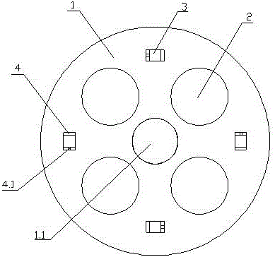
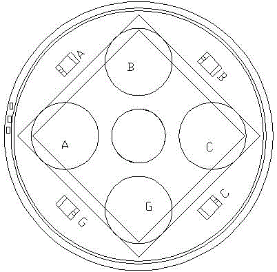
[0019] see Figure 1~3 , a kind of counterweight support that the present invention relates to, and described counterweight support comprises circular base 1, and the circular surface of described circular base 1 is uniformly provided with a plurality of counterweight mounting grooves 3, and described counterweight A counterweight is inserted in the installation groove 3, and ear plates 4 are vertically installed on both sides of the counterweight installation groove 3, and a positioning bolt hole 4.1 is arranged on one ear plate 4, which is screwed into the positioning bolt hole 4.1 The bolts of the counterweight are pressed against the other ear plate 4, so as to play a fastening role;

[0020] The above-mentioned counterweights are provided with a plurality of standard weights such as 1g, 2g, 5g, 10g, etc.;

[0021] A plurality of through holes 2 are evenly arranged on the circular surface of the circular base 1, which not only plays a role in reducing weight, but also doe...


PUM


Abstract

The invention discloses a counterweight support and a motor applying the support. The counterweight support comprises a circular pedestal (1). A round surface of the circular pedestal (1) is uniformly provided with a plurality of counterweight block installation grooves (3). The counterweight blocks are inserted into the counterweight block installation grooves (3). Two sides of the counterweight block installation grooves (3) are vertically provided with ear plates (4). One ear plate (4) is provided with a positioning bolt hole (4.1). A bolt screwed into the positioning bolt hole (4.1) compacts the counterweight blocks on the other ear plate (4). By using the counterweight support and the motor applying the support, operation is simple and convenient and a shape is beautiful.

Description

technical field [0001] The invention relates to a counterweight bracket, in particular to a weight block mounting bracket for adjusting the counterweight of a motor (synchronous motor, asynchronous motor) to achieve dynamic balance and a motor using the bracket, belonging to the technical field of motors. Background technique [0002] At present, motor systems are widely used in industrial production. In 2010, the installed capacity of various motors reached 750 million kilowatts, so motors have become indispensable power equipment in industrial production; The motor has an essential process: the dynamic balance correction of the motor; [0003] The conventional correction method is: de-weight or increase the weight of the motor rotor; because the de-weight will affect the magnetic flux of the electronic rotor, the method of adding weight is generally used nowadays; the usual method of adding weight is to add a nut to the pad, or put an irregular pad The block (or weight gl...

Claims


Application Information

Patent Timeline
IPC IPC(8): H02K7/04H02K1/28
CPCH02K7/04H02K1/28
Inventor 朱胡良
Owner 江阴市澳盛动力设备有限公司
Features
  • Generate Ideas
  • Intellectual Property
  • Life Sciences
  • Materials
  • Tech Scout
  • Unparalleled Data Quality
  • Higher Quality Content
  • 60% Fewer Hallucinations
Learn More