
Push-pull type selective laser melting (SLM) device forming cylinder capable of rising and falling

A laser selective melting and forming cylinder technology, which is applied in laser welding equipment, welding equipment, metal processing equipment, etc., can solve the difficulty of powder cleaning in fixed forming cylinders, the low efficiency of parts disassembly and powder collection, and the efficiency of preparation and cleaning Low-level problems, to achieve the effect of easy replacement, guaranteed convenience, and convenient operation

Active Publication Date: 2016-09-07
XI AN JIAOTONG UNIV +1
View PDF10 Cites 3 Cited by
  • Summary
  • Abstract
  • Description
  • Claims
  • Application Information

AI Technical Summary

Problems solved by technology

Due to this limitation, there are two main impacts on the SLM processing process: First, due to the limitation of the working position and space, the preparation and cleaning work efficiency for processing in the molding room is low, and it is easy to cause pollution to the molding room; the processing is completed The efficiency of post-

Method used


Image

  • Push-pull type selective laser melting (SLM) device forming cylinder capable of rising and falling
  • Push-pull type selective laser melting (SLM) device forming cylinder capable of rising and falling
  • Push-pull type selective laser melting (SLM) device forming cylinder capable of rising and falling

Examples


Example Embodiment

[0016] The present invention will be further described below in conjunction with the drawings and embodiments.

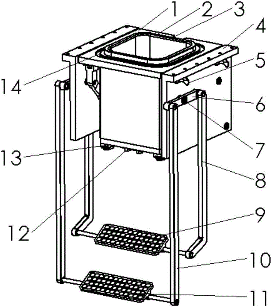
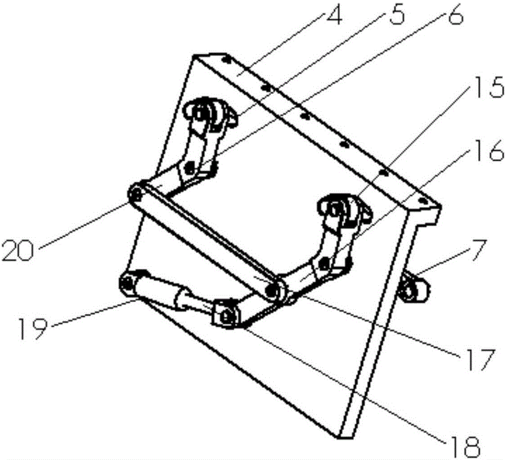
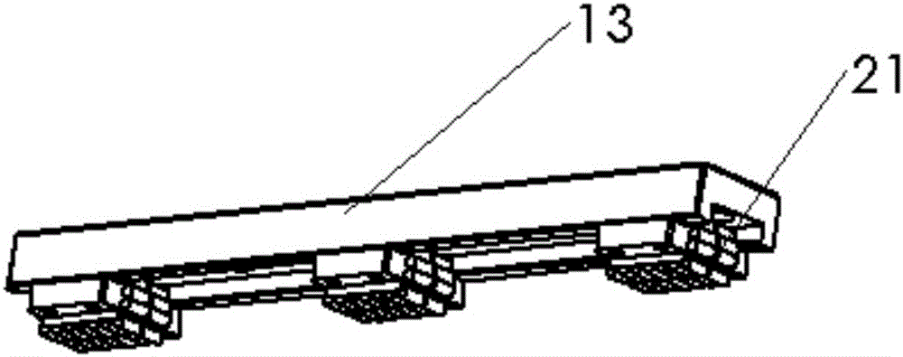
[0017] Reference figure 1 , figure 2 with image 3 , A lifting push-pull laser selective melting SLM equipment forming cylinder, including a forming cylinder body 1, the upper end of the forming cylinder body 1 is provided with a T-shaped boss 2, through the T-shaped boss 2 to realize the forming cylinder body 1 and the laser selective melting SLM For the guiding and docking of the molding chamber of the equipment, the lower end of the molding cylinder body 1 is provided with a tapered guide block 12 in the horizontal pull-out direction, and the outer extension part of the rear part of the molding cylinder body 1 is provided with a tapered guide positioning groove 3. A movable roller block 13 is provided, and three roller racks 21 are provided on the movable roller block 13. The guiding and movement of the forming cylinder body 1 is realized by the tapered guide block...


PUM


Abstract

A push-pull type selective laser melting (SLM) device forming cylinder capable of rising and falling comprises a forming cylinder body. A T-shaped boss is arranged at the upper end of the forming cylinder body. Guide and butt joint of the forming cylinder body and a selective laser melting (SLM) device forming chamber are achieved through the T-shaped boss. Conical guide blocks are arranged at the lower end of the forming cylinder body in the horizontal pull-out direction. A conical guide positioning groove is formed in the outwards-extending part on the rear portion of the forming cylinder body. The left side and the right side of the lower end of the forming cylinder body are each provided with a movable pin roller block. Pin roller frames are arranged on the movable pin roller blocks. The left side and the right side of the forming cylinder body are each provided with a supporting plate. Lifting mechanisms are connected to the supporting plates. By means of the push-pull type selective laser melting (SLM) device forming cylinder, the moving and positioning functions of the forming cylinder in the horizontal direction can be achieved, the lifting and self-locking functions of the forming cylinder in the vertical direction can be achieved, and therefore separation of the forming cylinder and the forming chamber before and after processing is achieved, convenience of operation is achieved, the processing efficiency of SLM is improved, and meanwhile pollution caused to the forming chamber in the traditional technological process is also reduced.

Description

technical field [0001] The invention belongs to the technical field of laser selective melting (SLM) for additive manufacturing, and in particular relates to a liftable push-pull type laser selective melting SLM equipment forming cylinder. Background technique [0002] Laser selective melting (SLM) is one of the research hotspots in the field of additive manufacturing technology. As we all know, the manufacturing efficiency of laser selective melting is not only related to the part size and processing speed, but also related to other auxiliary programs. The larger the part size, the processing cycle The longer; the faster the laser processing speed, the shorter the processing cycle. [0003] At present, in the laser selective melting process, the scanning speed of the laser can reach above 2000mm / s, which greatly improves the processing efficiency. However, affected by the overall size of the SLM equipment, the volume of the forming chamber and the position of the forming cy...

Claims


Application Information

Patent Timeline
IPC IPC(8): B23K26/00B23K26/34B23K26/70
CPCB23K26/00B23K26/342B23K26/702
Inventor 曹毅杨东李涤尘范长超张博李玉哲
Owner XI AN JIAOTONG UNIV
Learn More