
Front mold core plate structure

A front-mold core and plate structure technology, applied in the field of front-mold core plate structure, can solve problems affecting product forming accuracy, reduce the probability of bruising, avoid assembly errors, and improve precision

Inactive Publication Date: 2016-09-07
SUZHOU HUACHUAN PLASTIC MOLD PROD FACTORY
View PDF3 Cites 0 Cited by
  • Summary
  • Abstract
  • Description
  • Claims
  • Application Information

AI Technical Summary

Problems solved by technology

The front core plate structure of the existing mold generally includes a core plate, a cavity plate and a rear core plate arranged in sequence from bottom to bottom. The product model cavity is formed after the insert is installed in the middle of the core combination. Therefore, the core combination The accuracy after assembly seriously affects the product forming accuracy, so it is necessary to study a high-precision front core plate structure

Method used


Image

  • Front mold core plate structure
  • Front mold core plate structure

Examples


Embodiment Construction

[0018] The present invention is described below in conjunction with accompanying drawing.

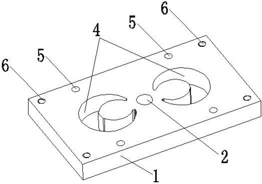
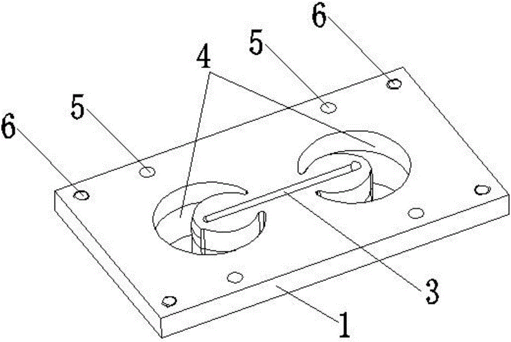
[0019] Front mold core plate structure of the present invention, as attached figure 1 , 2 As shown, it includes a front core plate main body 1 in the shape of a cuboid; the middle part of the front core plate main body is provided with a main channel hole 2; the main channel hole 2 runs through the front core plate main body 1; The middle part of the bottom end surface of the plate main body 1 is provided with a transverse flow channel 3, and the cross section of the transverse flow channel 3 is semicircular; the main channel hole 2 is connected with the transverse flow channel 3; There are two left and right symmetrical insert cavities 4, the insert cavities 4 are crescent-shaped; the two insert cavities 4 are located on the left and right sides of the transverse flow channel 3; A plurality of positioning pin holes 5 are provided; the positioning pin holes 5 pass through the main bod...


PUM


Abstract

The invention discloses a front mold core plate structure. The front mold core plate structure comprises a mold core plate body. A main runner hole is formed in the middle portion of the front mold core plate body and penetrates the front mold core plate body. A transverse runner is formed in the middle portion of the bottom end face of the front mold core plate body. The main runner hole communicates with the transverse runner. The front mold core plate body is further provided with two insert cavities symmetric left and right. The two insert cavities are located in the left side and the right side of the transverse runner. The front mold core plate body is further provided with a plurality of positioning pin holes penetrating the front mold core plate body. According to the front mold core plate structure, the insert cavities in the middle portions of the front mold core plate structure are designed to be in a crescent shape and are matched with crescent inserts, the bumping-damage probability of the inserts during assembly can be reduced to the maximum degree, and mounting and dismounting can be convenient. The insert cavities in the middle portions of a mold core combination are cut and machined through slow wires, and after the front mold core plate body, a mold cavity plate and a rear mold core plate are positioned through positioning pins, slow wire cutting machining is conducted in place, wherein the front mold core plate body is matched with the mold cavity plate and the rear mold core plate; and the assembly error is effectively avoided, and the precision of the front mold core plate structure can be obviously improved.

Description

technical field [0001] The invention relates to the structural technical field of plastic product molds, in particular to the structure of a front mold core plate. Background technique [0002] With the continuous improvement of technology and the rapid development of the plastic product industry, the diversified structure of various plastic parts is becoming more and more complex, the quality requirements are becoming more and more stringent, the requirements for the plastic product industry are getting higher and higher, and the competition is also increasing. The more intense it is, how to ensure that there are no abnormalities in the production process of similar plastic products, and to maximize the effective and stable production cycle of product processing. The front core plate structure of the existing mold generally includes a core plate, a cavity plate and a rear core plate arranged in sequence from bottom to bottom. The product model cavity is formed after the ins...

Claims


Application Information

Patent Timeline
Patent Type & Authority Applications(China)
IPC IPC(8): B29C45/27B29C45/32B29C45/36B29C33/76B29C33/38
CPCB29C33/3842B29C33/76B29C45/2708B29C45/32B29C45/36B29C2045/2709
Inventor 谢永华
Owner SUZHOU HUACHUAN PLASTIC MOLD PROD FACTORY
Learn More