Roadbed drainage structure for municipal administration road and construction method of roadbed drainage structure

A technology for drainage structures and municipal roads, applied in drainage structures, roads, roads, etc., can solve problems affecting road quality, rainwater infiltration, and construction of low-lying subgrade soils, and achieve easy popularization, rapid process, and improved road quality. Effect

Active Publication Date: 2016-09-07
中冶南方城市建设工程技术有限公司 +1
View PDF5 Cites 5 Cited by
  • Summary
  • Abstract
  • Description
  • Claims
  • Application Information

AI Technical Summary

Problems solved by technology

[0002] During the construction of municipal roads, when the topographic height difference of new roads changes greatly, the soil located on higher terrains will accumulate water in the soil due to factors such as rainfall, and will slowly pass through the interior of the soil layer due to the terrain difference and flow into the In the soil layer of lower terrain, the construction of low-lying subgrade soil is affected, and municipal roads are different from ordinary roads, especially for roads located in the center of the city. There are mostly enterprises and buildings on both sides of the road, and there is no side slope. The accumulated water cannot be discharged from the slopes on both sides by traditional methods. If it cannot be removed in time, it will often cause diseases such as subgrade settlement in the later stage, which will seriously affect the road quality.
[0003] The traditional method of dealing with subgrade water seepage is often to set up blind ditches to drain the water through the lateral slope, or to naturally seep out all the high-level water and dry the low-level subgrade soil before compacting the subgrade. However, there is often no such method for municipal roads. For side slopes, the method of draining to both sides of the road is not applicable and the process is complicated. The method of natural infiltration takes a long time and is not suitable for rainy areas. It is possible that new rainwater will infiltrate before the upper stagnant water is drained.

Method used


Image

  • Roadbed drainage structure for municipal administration road and construction method of roadbed drainage structure
  • Roadbed drainage structure for municipal administration road and construction method of roadbed drainage structure
  • Roadbed drainage structure for municipal administration road and construction method of roadbed drainage structure

Examples


Embodiment Construction

[0023] In order to more clearly illustrate the purpose, technical solutions and advantages of the present invention, the present invention will be further described in detail below in conjunction with the accompanying drawings and embodiments.

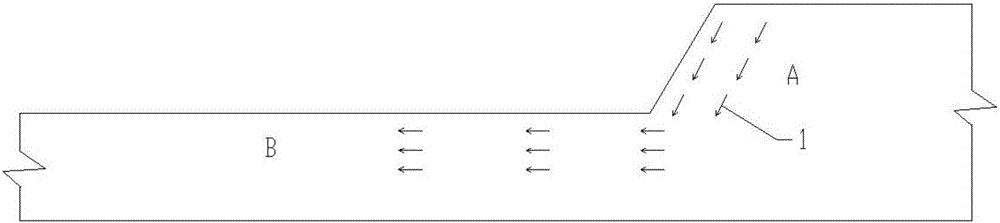
[0024] Such as figure 1 It shows the seepage of untreated upper stagnant water. The left side represents the low-lying road section B, and the right side represents the high-lying road section B. The height difference between the two road sections causes the upper-layer stagnant water in the high-lying subgrade soil to gather and seep to the low-lying road In roadbed soil.

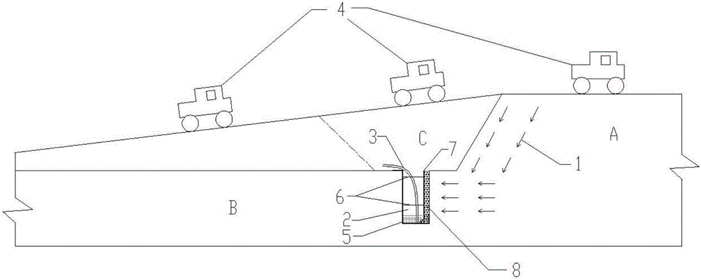
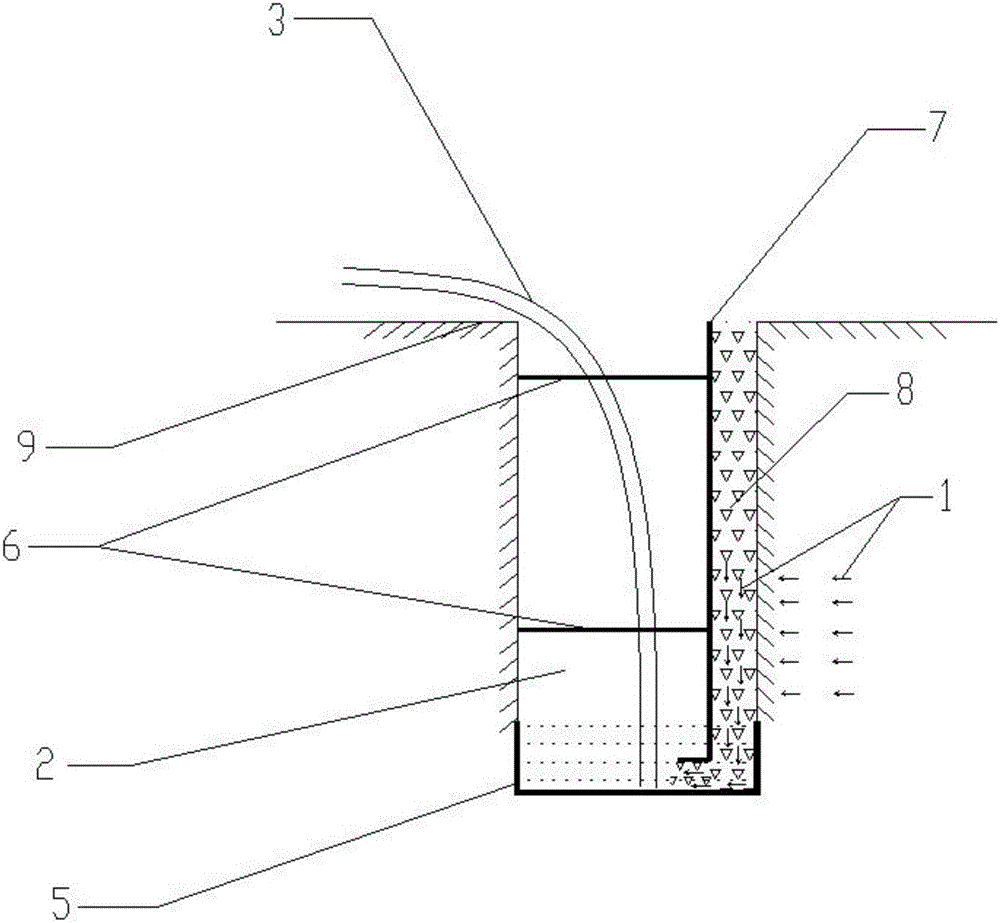
[0025] Figure 2~3 Shown is the subgrade drainage structure that the present invention adopts in getting rid of the construction process of upper stagnant water:

[0026] A municipal road subgrade drainage structure, comprising a high terrain section A and a low terrain section B, an intercepting ditch 2 is set at the slope foot of the higher terrain section A, a...


PUM

PropertyMeasurementUnit
Depthaaaaaaaaaa
Particle sizeaaaaaaaaaa
Widthaaaaaaaaaa

Abstract

The invention discloses a roadbed drainage structure for a municipal administration road. The roadbed drainage structure comprises a high-elevation road segment and a low-elevation road segment. A intercepting drain is formed in the position of a slope toe of the high-elevation road segment, and a seepage-proof composite geomembrane is laid at the bottom of the intercepting drain; a layer of gravel is laid at the position, close to the high-elevation side, of the bottom of the intercepting drain; a baffle is arranged at the position, 30 cm away from the inner wall of the high-elevation side, in the intercepting drain; and a water suction pipe is further arranged in the intercepting drain. The invention further provides a construction method of the roadbed drainage structure. By the adoption of the roadbed drainage structure and the construction method of the roadbed drainage structure, a roadbed perched water problem is solved, meanwhile, the normal procedure of roadbed compaction is not affected, and it is guaranteed that the construction schedule is not affected.

Description

technical field [0001] The invention relates to the technical field of municipal road engineering, in particular to a municipal road embankment drainage structure and a construction method thereof. Background technique [0002] During the construction of municipal roads, when the topographic height difference of new roads changes greatly, the soil located on higher terrains will accumulate water in the soil due to factors such as rainfall, and will slowly pass through the interior of the soil layer due to the terrain difference and flow into the In the soil layer of lower terrain, the construction of low-lying subgrade soil is affected, and municipal roads are different from ordinary roads, especially for roads located in the center of the city. There are mostly enterprises and buildings on both sides of the road, and there is no side slope. The accumulated water cannot be discharged from the side slopes by traditional methods. If it cannot be removed in time, it will often ...

Claims


Application Information

Patent Timeline
IPC IPC(8): E01C3/06E01F5/00E03F5/04
CPCE01C3/06E01F5/00E03F5/0401Y02A30/60
Inventor 蒋远浩
Owner 中冶南方城市建设工程技术有限公司
Why Eureka
Try Eureka