

Industrial equipment glass lens gasket
A technology for glass sight glass gaskets and industrial equipment, applied in the field of sight glass gaskets, can solve problems such as affecting the normal operation of the equipment, not using excessive force, and glass sight glass leakage, etc. The effect of using efficiency
Inactive Publication Date: 2016-09-07
FEIXI XINSHAN MACHINERY FACTORY
View PDF6 Cites 0 Cited by
- Summary
- Abstract
- Description
- Claims
- Application Information
AI Technical Summary
Problems solved by technology
[0003] Glass sight glass is needed in many industrial equipments to observe the internal conditions of the equipment. The glass sight glass is generally round or long. The equipment is sealed with asbestos plate gaskets and PTFE plate gaskets, but due to the glass Due to the fragility of the sight glass, the sealing surface is designed to be relatively narrow. When using conventional gaskets, excessive force cannot be used during the fastening process. As a result, the glass sight glass of the equipment often leaks, which affects the normal operation of the equipment. How to avoid it? This practical problem is a headache for many equipment manufacturers.
Method used
View moreImage
Smart ImageViewing Examples

Examples
Embodiment Construction
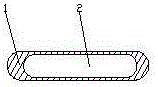
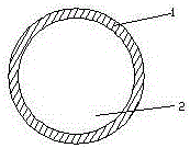
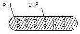
[0013] refer to Figure 1-2 In the past, the gasket viewed hole 2 as the surface opening, and the gasket was easily deformed due to the small area of the sealing surface 1; refer to Figure 3-4 Among them, the gasket sees the hole 2-2 as a point opening, and the area of the sealing surface 2-1 does not change, but the overall strength of the gasket is increased, and it is not easy to deform. Figure 3-4 The viewing holes in the hole are processed by a drilling machine, and the arrangement must be regular. The diameter of the viewing hole is generally φ6-8 mm.
Login to View More PUM
 Abstract
The invention discloses an industrial equipment glass lens gasket, and relates to the technical field of lens gaskets needed by industrial equipment. The industrial equipment glass lens gasket comprises a gasket sealing surface (2-1) and gasket viewing holes (2-2); and the gasket viewing holes (2-2) are uniformly formed in the gasket sealing surface (2-1). As a perforating mode on the gasket is changed, the gasket is not easy to deform, is convenient for installation, improves the use efficiency, and prolongs the equipment operation period.
Description
[0001] technical field [0002] The invention relates to the technical field of sight glass gaskets used in industrial equipment, in particular to a glass sight glass gasket for industrial equipment. Background technique [0003] Glass sight glass is needed in many industrial equipments to observe the internal conditions of the equipment. The glass sight glass is generally round or long. The equipment is sealed with asbestos plate gaskets and PTFE plate gaskets, but due to the glass Due to the fragility of the sight glass, the sealing surface is designed to be relatively narrow. When using conventional gaskets, excessive force cannot be used during the fastening process. As a result, the glass sight glass of the equipment often leaks, which affects the normal operation of the equipment. How to avoid it? This practical problem is a headache for many equipment manufacturers. Contents of the invention [0004] The purpose of the present invention is to provide a glass sight ...
Claims
Login to View More Application Information
Patent Timeline
 IPC IPC(8): F16J15/06
CPCF16J15/06
Inventor周俊
OwnerFEIXI XINSHAN MACHINERY FACTORY