

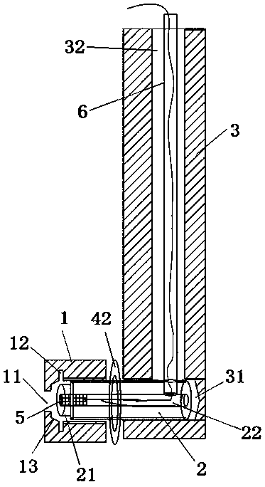
An electrode device for detecting the electrochemical performance of porous coating materials
A porous coating and electrode device technology, applied in the field of material performance testing equipment, can solve the problems of different electrolyte temperature and substrate temperature, affecting the pore structure and porosity of the coating, affecting the accuracy of the detection results, etc., so as to avoid detection errors. Accuracy, good thermal conductivity and long service life
- Summary
- Abstract
- Description
- Claims
- Application Information
AI Technical Summary
Problems solved by technology
Method used
Image

Examples
Embodiment 1
[0056] According to the design of each component of the electrode device for detecting the electrochemical performance of the porous coating material, it is processed in the best implementation mode, and processed into a suitable size according to the actual detection environment, as follows:
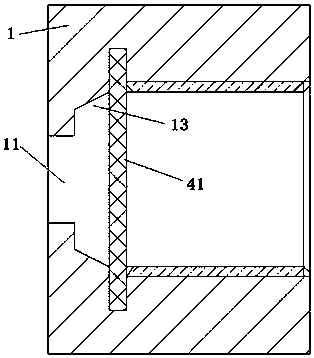
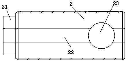
[0057] Front gland 1: It is a cylindrical shape with one end and one open made of polytetrafluoroethylene, with a total length of 30mm, an outer diameter of 40mm, and an inner diameter of 20mm. Electrochemical experiments carried out. The outer wall is provided with knurling to facilitate rotation installation. A metal protective sleeve is embedded in the opening, and the protective sleeve has an M20 internal thread with a thread length of 20mm. With the design of embedded metal protective sleeve, the front end of the conductive column 2 of M20 can be directly threaded. The threaded metal protective sleeve used can provide good stability under high-strength stress environment after re...
Embodiment 2
[0066]The electrode device with the electrochemical properties of the porous coating material prepared in Example 1 was used to carry out a corrosion comparison experiment to verify the reliability of the device. The principle of the experiment is to conduct a corrosion comparison experiment in physiological saline simulating the human environment by installing a titanium sheet with a thickness of 1mm and a diameter of 14mm. Observe the surface morphology of the titanium sheet before and after the experiment and compare the experimental results. The electrolyte is physiological saline with a mass concentration of 0.9%; the power supply is a 30V DC power supply; the sample is a titanium sheet with a thickness of 1mm and a diameter of 14mm; other devices use existing coating materials such as electrochemical experiment electrode molds and temperature display gauges.
PUM
| Property | Measurement | Unit |
|---|---|---|
| length | aaaaa | aaaaa |
| thickness | aaaaa | aaaaa |
| thickness | aaaaa | aaaaa |
Abstract
Description
Claims
Application Information