Test system and method suitable for high stability radio frequency signal power stability

A power stability and radio frequency signal technology, which is used in the measurement of electrical power, electrical devices, measuring devices, etc., can solve the problem that the stability characteristics cannot meet the test requirements of high stability radio frequency signal power stability, and the measurement accuracy of the power meter is limited. Stability and other issues, to achieve the effect of improving confidence and validity, real-time measurement

Active Publication Date: 2018-06-26
THE 41ST INST OF CHINA ELECTRONICS TECH GRP
View PDF6 Cites 0 Cited by
  • Summary
  • Abstract
  • Description
  • Claims
  • Application Information

AI Technical Summary

Problems solved by technology

[0004] The power stability of existing radio frequency signals is usually obtained by using a microwave power meter for testing and calculation based on the power measurement mode. It can be seen from the above that when the amount of test data is large enough, the power measurement has the greatest impact on the power stability results. The data results, while the power measurement data results are limited by the power meter measurement accuracy and stability and other index characteristics
When the power (amplitude) stability of the radio frequency signal reaches 0.1% or even higher, according to the usual mode of measurement calibration, to achieve effective test evaluation, the power measurement accuracy and stability and other indicators should reach at least 0.03% ~ 0.01% Or a higher order, but the current traditional microwave power meter's highest accuracy index of 0.2% and the unspecified stability characteristics cannot meet the test requirements of high stability RF signal power stability

Method used


Image

  • Test system and method suitable for high stability radio frequency signal power stability
  • Test system and method suitable for high stability radio frequency signal power stability
  • Test system and method suitable for high stability radio frequency signal power stability

Examples


Embodiment Construction

[0022] The present invention will be further described below in conjunction with the accompanying drawings and embodiments.

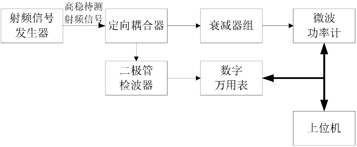
[0023] like figure 1 As shown, the test system suitable for high stability radio frequency signal power stability includes directional coupler, attenuator group, microwave power meter, host computer, high-precision digital multimeter and diode detector. The directional coupler and attenuator group , Microwave power meters are connected in series sequentially, and the upper computer performs system application measurement and control on the microwave power meter and the high-precision digital multimeter respectively through the program-controlled bus. The multimeter is connected, and the diode detector is a gallium arsenide diode detector.

[0024] The diode detector is arranged in the constant temperature chamber.

[0025] The gallium arsenide diode detector utilizes square law characteristics for detection. The detection method with square law chara...


PUM


Abstract

The invention discloses a test system and method suitable for high stability radio frequency signal power stability. The system includes a directional coupler, an attenuator group, a microwave power meter, a host computer, a high-precision digital multimeter and a diode detector. The directional coupler is connected in series with the attenuator group and the microwave power meter in turn, and the host computer performs system application measurement and control on the microwave power meter and the high-precision digital multimeter respectively through the program control bus, and the coupling end of the directional coupler is connected with the diode detector , the diode detector is connected with a high-precision digital multimeter, and the diode detector is a gallium arsenide diode detector. The beneficial effects of the present invention are: the present invention realizes the test and evaluation target of radio frequency signal power stability obtained synchronously without distortion through the test of the detection voltage stability, and the design of the constant temperature cavity and the gallium arsenide device makes the power of the input radio frequency signal constant In some cases, the detection voltage is affected by temperature changes to a minimum.

Description

technical field [0001] The invention relates to the technical field of microwave testing, in particular to a testing system and method suitable for high stability radio frequency signal power stability. Background technique [0002] Power is one of the basic parameters in the high-frequency and microwave fields, which characterizes the transmission characteristics of high-frequency and microwave sources, mainly including index characteristics such as power accuracy and power stability. In some practical applications that require high stability of the output power (amplitude) of the RF signal, especially when the stability of the power (amplitude) reaches 0.1% or even higher, how to effectively test and trace the stability characteristics has become a problem. Technical problems that urgently need to be solved. [0003] At present, the power accuracy and power stability test of the radio frequency signal is usually carried out by a microwave power meter, and the radio freque...

Claims


Application Information

Patent Timeline
Patent Type & Authority Patents(China)
IPC IPC(8): G01R21/00H04B17/15
CPCG01R21/00H04B17/15
Inventor 郭敏吴家亮樊晓腾刘盛
Owner THE 41ST INST OF CHINA ELECTRONICS TECH GRP
Why Eureka
Try Eureka