Check patentability & draft patents in minutes with Patsnap Eureka AI!

Grounding network design method for reducing impact grounding resistance of grounding network

A technology of impact grounding resistance and design method, applied in the direction of measuring resistance/reactance/impedance, measuring electrical variables, connecting contact materials, etc., can solve the problem of poor stability of resistance reduction, high operation and maintenance costs, and difficulty in effectively reducing the impact of tower grounding grids Grounding resistance and other issues to achieve the effect of reducing impact grounding resistance

Inactive Publication Date: 2016-09-07
ELECTRIC POWER RES INST STATE GRID JIANGXI ELECTRIC POWER CO +2
View PDF6 Cites 10 Cited by
  • Summary
  • Abstract
  • Description
  • Claims
  • Application Information

AI Technical Summary

Problems solved by technology

However, the service life of the ionic grounding rod is short, and inorganic salt needs to be regularly added to the copper pipe, and the operation and maintenance costs are high.
[0005] Through comparison, it can be seen that the existing resistance reduction methods have problems such as waste of resources and poor stability of resistance reduction, and it is difficult to effectively reduce the impact grounding resistance of the tower grounding grid

Method used


Image

  • Grounding network design method for reducing impact grounding resistance of grounding network
  • Grounding network design method for reducing impact grounding resistance of grounding network
  • Grounding network design method for reducing impact grounding resistance of grounding network

Examples


Embodiment Construction

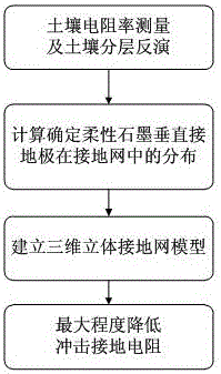
[0025] figure 1 It is the flow chart of the specific embodiment of the present invention, from which it can be seen that the implementation process of the invention is mainly divided into 4 steps:

[0026] (1) Soil resistivity measurement and soil layer inversion;

[0027] (2) Calculate and determine the distribution of flexible graphite vertical grounding electrodes in the grounding grid;

[0028] (3) Establish a three-dimensional grounding grid model;

[0029] (4) Minimize the impact grounding resistance.

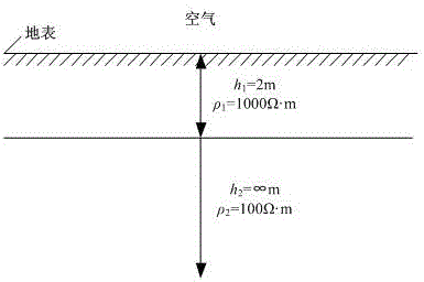
[0030] The grounding grid design of a tower is taken as an example below.

[0031] Assume that the terrain of the tower is figure 2 The soil stratification is shown, in which the upper soil depth is 2m, the soil resistivity is 1000Ω·m, the lower soil depth is infinite, and the soil resistivity is 100Ω·m.

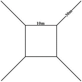
[0032] image 3 It is a commonly used form of grounding grid for transmission line tower grounding grids, and does not use flexible graphite vertical grounding e...


PUM


Abstract

The invention relates to a grounding network design method for reducing the impact grounding resistance of the pole grounding network. The soil resistivity in the surrounding a pole is measured to inverse the layered state of the soil, CDEGS software is utilized to determine distribution of flexible graphite vertical earth electrodes in the pole grounding network via a lot of computation, a 3D transmission-line power grounding network model is established, different designs of the pole grounding network are realized, and the impact grounding resistance of the grounding network is reduced to the largest extent. According to different landform conditions, 3D grounding network design is carried out on each pole, the impact grounding resistance is reduced to the largest extent, reference for pole grounding network construction is provided for power departments, and the method is suitable for poles of different voltage levels.

Description

[0001] Technical field [0002] The present invention involves a ground -network design method that reduces the ground resistance of the tower to the ground resistance. Background technique [0003] In recent years, with the continuous development of modern power systems, the length of overhead lines has continued to expand, and it is exposed to the wilderness. It is easy to be attacked by lightning. From the statistical situation, in the statistics of the failure classification of power grids in my country, the number of cards caused by lightning strikes accounts for about the operation of the high -voltage line operation. 40%to 70%of the total number of branches, especially in areas with high thunder, high soil resistivity, and complex terrain, and the accident rate caused by lightning strike lines is higher.In the transmission line, the grounding of the pole tower is an important means of preventing lightning strikes in the transmission line. Reliable grounding can improve the...

Claims


Application Information

Patent Timeline
IPC IPC(8): G01R27/02H01R4/66
CPCG01R27/02H01R4/66
Inventor 周友武徐宁阮江军黄道春龙明洋郭志锋郭泉辉张宇胡京
Owner ELECTRIC POWER RES INST STATE GRID JIANGXI ELECTRIC POWER CO
Features
  • R&D
  • Intellectual Property
  • Life Sciences
  • Materials
  • Tech Scout
  • Unparalleled Data Quality
  • Higher Quality Content
  • 60% Fewer Hallucinations
Learn More