Single-beam image transmission optical fiber and application thereof

A technology of optical fiber for image transmission and outgoing optical fiber, applied in the field of application, can solve the problems of not being able to meet the needs of viewing, not being able to fundamentally improve the imaging quality of the fiber bundle, not being able to effectively apply video glasses, etc., and achieve the effect of reducing weight

Active Publication Date: 2016-09-07
漳州市阿思星谷电子科技有限公司
View PDF8 Cites 1 Cited by
  • Summary
  • Abstract
  • Description
  • Claims
  • Application Information

AI Technical Summary

Problems solved by technology

[0002] Traditional fiber optic imaging includes fiber bundle imaging and photoelectric conversion imaging; in which each fiber in the fiber bundle transmits one pixel of the image, so the imaging quality (resolution) depends on the diameter of the fiber and the distance between adjacent fibers; because Due to this limitation, the imaging quality of the fiber bundle cannot be fundamentally improved.
[0003] Because of the above defects of optical fiber, it cannot be effectively applied to video glasses; on the other hand, in order to meet the wearable needs of current video glasses, the video canvas area generally does not exceed 200 square centimeters, and the video in it needs to be magnified up to 10,000 times , even the CCD display with the highest resolution cannot meet the effective viewing needs

Method used


Image

  • Single-beam image transmission optical fiber and application thereof
  • Single-beam image transmission optical fiber and application thereof
  • Single-beam image transmission optical fiber and application thereof

Examples


Embodiment 1

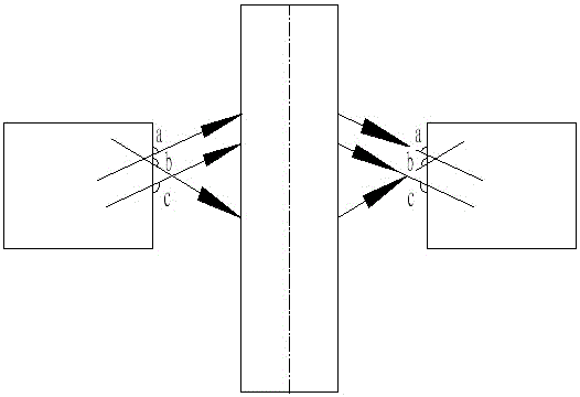
[0023] Such as Figure 1-3 A kind of single-bundle image-transmitting optical fiber shown is characterized in that: an incident optical fiber and an outgoing optical fiber are provided, and the incident optical fiber and the outgoing optical fiber have the same diameter and the same length; A ray symmetry processing device is provided; the ray symmetry processing device makes all the incident rays passing through the ray symmetry processing device and the symmetry axes of the outgoing rays be on the same plane.

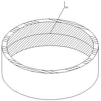
[0024] The light symmetry processing device is provided with a group of concentric rings ranging from small to large, and a mirror is arranged on the inner wall of the ring.

[0025] The concentric rings are embedded in a material having the same refractive index as the optical fiber.

[0026] The overall shape of the incident optical fiber and the outgoing optical fiber is axisymmetric.

[0027] working principle:

[0028] After the light enters from the incident ...

Embodiment 2

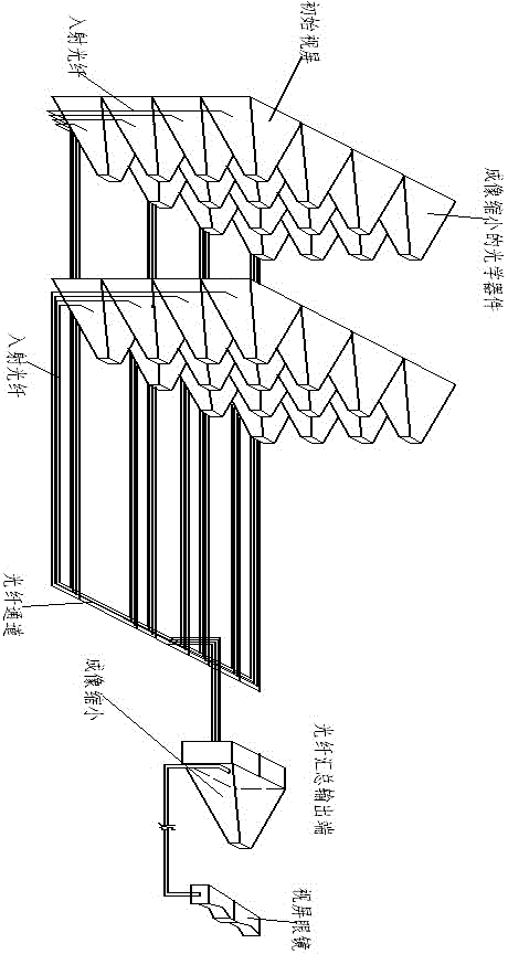
[0033] Such as figure 2 The video glasses system that uses a single image-transmitting optical fiber as claimed in the claim is characterized in that: a video processing unit and a head-mounted eyepiece; the video processing unit contains 2 or more initial video screens, and the The initial screen is provided with one or more optical devices with imaging reduction function, so that the image on the initial screen is reduced in proportion to output from the output end a of the optical device; the output end a of the optical device is connected to the incident end of the incident optical fiber; The outgoing ends of the outgoing optical fiber are arranged in order to output and directly or indirectly connected to the head-mounted eyepiece.

[0034] The output ends of two or more outgoing fibers are connected together to an optical device with imaging reduction function, a single image-transmitting optical fiber is connected to the output end of the optical device, and the single...


PUM


Abstract

The invention relates to a single-beam image transmission optical fiber, which is characterized by comprising an incident optical fiber and an emergent optical fiber, wherein the incident optical fiber and the emergent optical fiber are identical in diameter and length, an emergent end of the incident optical fiber and an incident end of the emergent optical fiber are provided with a light symmetric processing device therebetween; and the light symmetric processing device enables symmetry axes of all incident light passing through the light symmetric processing device and the emergent light thereof to be on the same plane. The single-beam image transmission optical fiber realizes that a single optical fiber transmits images directly without going through photoelectric conversion by adopting a technology of light symmetric processing according to a principle that the light path is reversible, thereby enabling the image quality of an eyepiece to infinitely approach to an original video source.

Description

technical field [0001] The invention mainly relates to a light guiding optical fiber, and applications such as video glasses using the optical fiber technology. Background technique [0002] Traditional fiber optic imaging includes fiber bundle imaging and photoelectric conversion imaging; in which each fiber in the fiber bundle transmits one pixel of the image, so the imaging quality (resolution) depends on the diameter of the fiber and the distance between adjacent fibers; because Due to this limitation, the imaging quality of the fiber optic bundle cannot be fundamentally improved. [0003] Because of the above defects of optical fiber, it cannot be effectively applied to video glasses; on the other hand, in order to meet the wearable needs of current video glasses, the video canvas area generally does not exceed 200 square centimeters, and the video in it needs to be magnified up to 10,000 times , just to even the CCD display screen with the highest resolution, it can't...

Claims


Application Information

Patent Timeline
Patent Type & Authority Applications(China)
IPC IPC(8): G02B6/06G02B27/01
CPCG02B6/06G02B27/0172G02B2027/0178
Inventor 黄得锋
Owner 漳州市阿思星谷电子科技有限公司
Why Eureka
Try Eureka