
A battery pack module and its fixing method

A technology for battery packs and lithium batteries, which is applied in battery pack components, electrolyte storage battery manufacturing, non-aqueous electrolyte storage batteries, etc. It can solve the problems affecting the flatness of the manifold, the long time required, the manifold falling off, etc., to ensure stability Sex and reliability, good for weight loss, anti-shedding effect

Active Publication Date: 2019-05-07
上海南库新能源技术有限公司
View PDF5 Cites 0 Cited by
  • Summary
  • Abstract
  • Description
  • Claims
  • Application Information

AI Technical Summary

Problems solved by technology

[0003] At this stage, the status quo of fixing the battery pack module is as follows: firstly, the contact surface between the manifold and the cell bracket is fully bonded with glue. The disadvantages are: 1) the glue itself and the labor cost required for bonding are expensive; 2) the glue It takes a long time to completely dry, which virtually lengthens the production time; 3) The reliability of simple glue bonding is not high. Once the glue fails, the manifold will fall off, and the consequences will be disastrous.
Secondly, the battery bracket and the battery bracket are connected by screws and nuts. The disadvantages are: 1) The battery pack is in a long-term vibration environment, and the screw is in direct contact with the bus plate to be charged. Once the screw is loose, the charged screw and the bus board Sparks are generated due to vibration and collision, and the consequences will be disastrous
2) Due to the mechanical tightness of the screws, and because the material of the cell bracket is plastic, after the screw is tightened, the cell bracket will be squeezed and deformed, which will affect the flatness of the manifold and cause unnecessary damage to the actual production. troubled
Although it is also connected with plastic screws, the torque strength of the plastic screws is not enough

Method used


Image

  • A battery pack module and its fixing method
  • A battery pack module and its fixing method
  • A battery pack module and its fixing method

Examples


Embodiment Construction

[0035] The following will clearly and completely describe the technical solutions in the embodiments of the present invention with reference to the drawings in the embodiments of the present invention. Apparently, the described embodiments are only some of the embodiments of the present invention, but not all of them. Based on the embodiments of the present invention, all other embodiments obtained by persons of ordinary skill in the art without making creative efforts belong to the protection scope of the present invention.

[0036] Unless otherwise defined, the technical terms or scientific terms used herein shall have the usual meanings understood by those skilled in the art to which the present invention belongs. "First", "second", "third" and similar words used in the patent application specification and claims of the present invention do not indicate any order, quantity or importance, but are only used to distinguish different components . Likewise, words like "a" or "...


PUM


Abstract

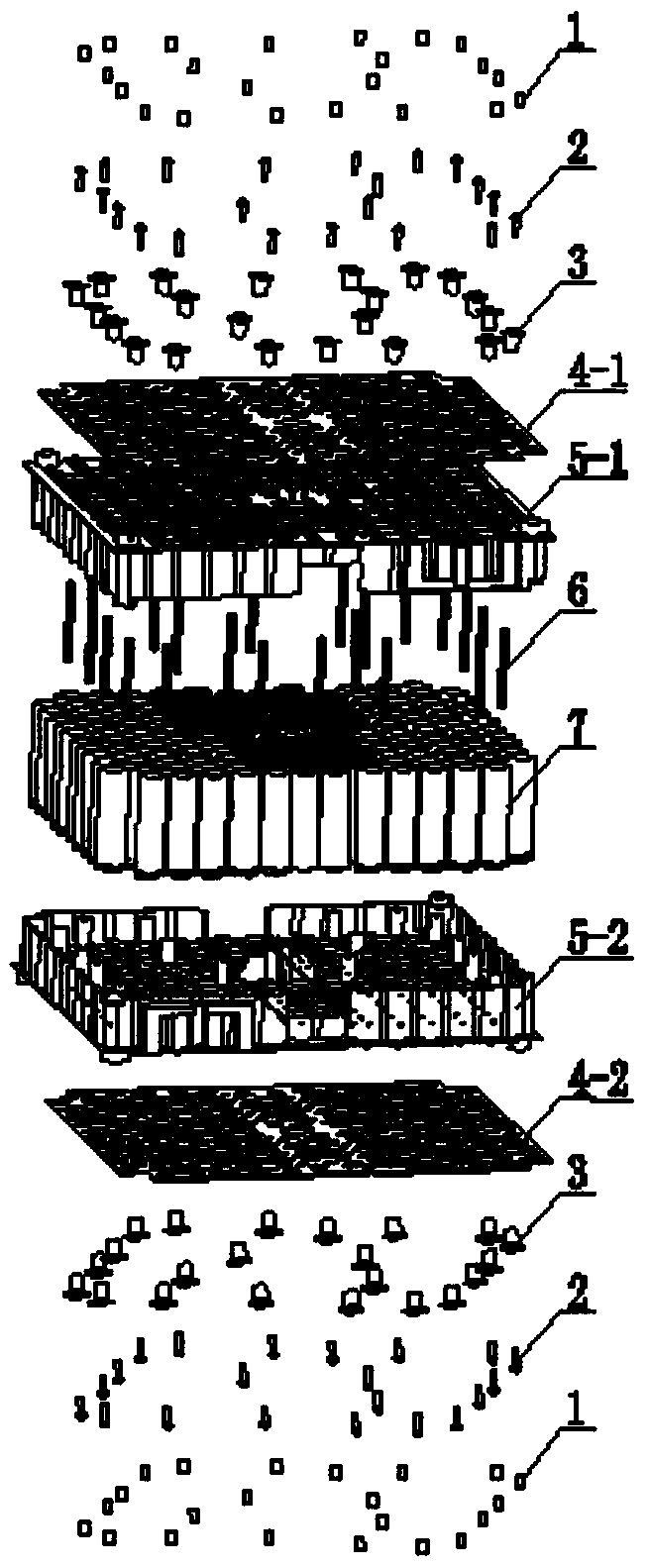
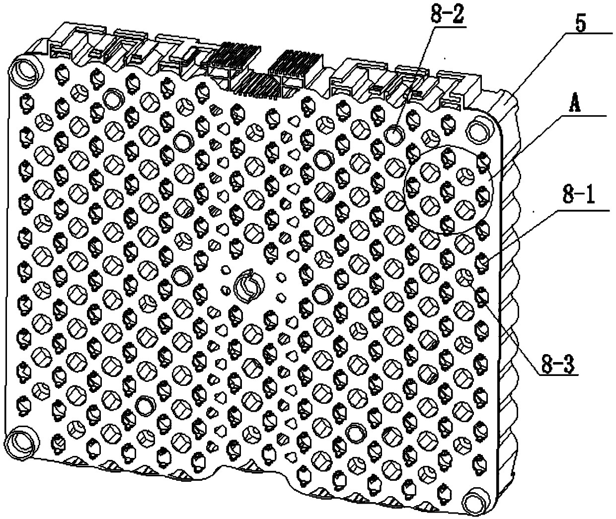
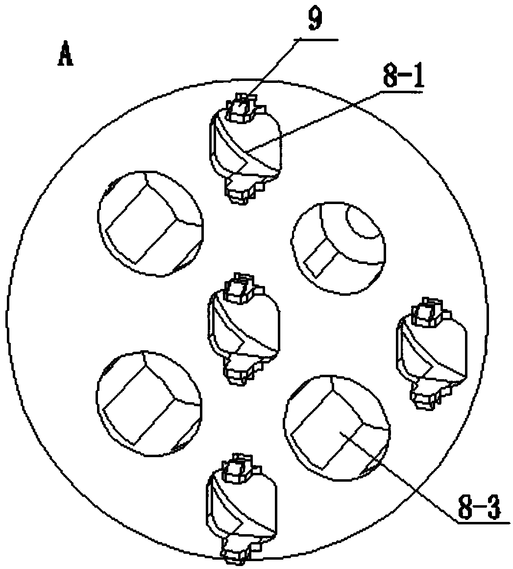
The present invention provides a battery pack module, comprising: two battery cell brackets, which can relatively fix cylindrical lithium batteries up and down; each battery cell bracket is equipped with a plurality of elastic buckles; A plurality of holes are left on each manifold, and the holes are divided into a first hole, a second hole and a third hole; wherein at least one of the elastic clips The buckle can be stuck on at least one of the first holes; a plurality of aluminum profile tubes, at least one of the aluminum profile tubes can pass through at least one of the second holes, and be inserted between adjacent cylindrical lithium batteries in the vertical direction The gap between the battery bracket and the manifold can be fixed; it can not only ensure the stability and reliability of the connection between the manifold and the cell bracket, but also avoid the damage caused by the loosening of screws.

Description

【Technical field】 [0001] The invention relates to the field of lithium ion batteries, in particular to a battery pack module and a fixing method thereof. 【Background technique】 [0002] At present, with the rapid development of new energy vehicles, the country is also promulgating relevant policies favorable to new energy vehicles, but the safety of vehicle battery packs is becoming more and more prominent in the structural design of battery packs, especially the safe fixing of battery pack modules Way. [0003] At this stage, the status quo of fixing the battery pack module is as follows: firstly, the contact surface between the manifold and the cell bracket is fully bonded with glue. The disadvantages are: 1) the glue itself and the labor cost required for bonding are expensive; 2) the glue It takes a long time to completely dry, which virtually prolongs the production time; 3) The reliability of simple glue bonding is not high. Once the glue fails, the manifold will fall...

Claims


Application Information

Patent Timeline
Patent Type & Authority Patents(China)
IPC IPC(8): H01M2/10H01M10/058H01M50/204
CPCH01M10/058H01M50/20Y02E60/10Y02P70/50
Inventor 曹键张保立张军
Owner 上海南库新能源技术有限公司
Learn More