
Hot chamber die casting machine with guiding structure

A hot-chamber die-casting machine and guide structure technology, which is applied in the field of hot-chamber die-casting machines, can solve the problems that the movable die and the fixed die cannot be closed, and affect the processing quality of castings, so as to improve the service life, prevent stress concentration, and improve quality. Effect

Inactive Publication Date: 2016-09-14
CHONGQING YINGRUISHENG DIE CASTING
View PDF0 Cites 1 Cited by
  • Summary
  • Abstract
  • Description
  • Claims
  • Application Information

AI Technical Summary

Problems solved by technology

[0002] With the rapid development of my country's automobile, motorcycle, home appliance and other industries, the shape of industrial products has become more and more complex while meeting the performance requirements, and the die-casting process can process products of various complex shapes, which can meet the requirements of the processing industry , the die-casting machine is divided into cold chamber die-casting machine and hot chamber die-casting machine. Compared with the cold chamber die-casting machine, the hot chamber die-casting machine has the advantages of simple structure, convenient operation, high productivity, stable process and impurities on the surface of the molten metal will not enter the pressure chamber so that the casting However, when the existing hot chamber die-casting machine clamps the movable mold and the fixed mold, the movable mold does not have any guiding structure when it approaches the fixed mold, which will easily lead to the inability of the movable mold and the fixed mold. Accurate position mold clamping, which in turn affects the processing quality of castings

Method used


Image

  • Hot chamber die casting machine with guiding structure

Examples


Embodiment Construction

[0011] The present invention will be described in further detail below by means of specific embodiments:

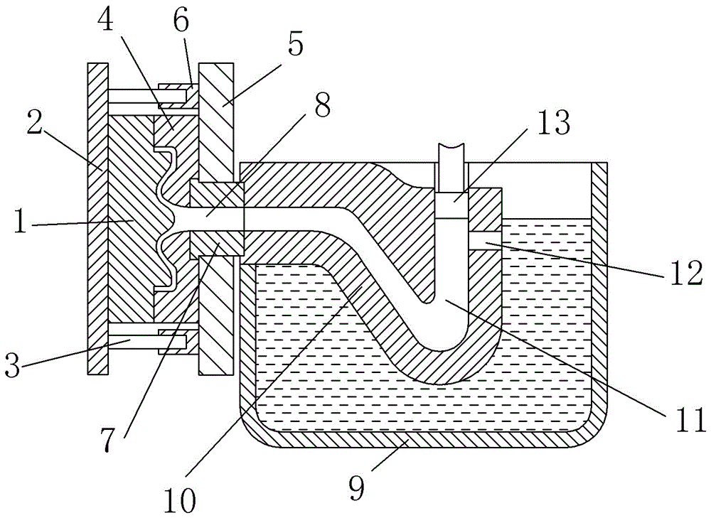
[0012] The reference signs in the drawings of the description include: moving mold 1, moving mold mounting plate 2, guide column 3, fixed mold 4, fixed mold mounting plate 5, guiding protrusion 6, connecting block 7, connecting channel 8, crucible 9, Pressure chamber 10, gooseneck channel 11, liquid inlet channel 12, injection head 13.

[0013] The embodiment is basically as attached figure 1 Shown: a hot chamber die-casting machine with a guide structure, including a moving die 1, a moving die mounting plate 2 is provided on the left side of the moving die 1, and the moving die 1 and the moving die mounting plate 2 are connected by screws. The upper and lower sides of the mold mounting plate 2 are symmetrically provided with two guide columns 3 with the movable mold 1 as the center, and the guide columns 3 are cylindrical guide columns 3 .

[0014] The fixed mold 4 is ...


PUM


Abstract

The invention discloses a hot chamber die casting machine with a guiding structure. The hot chamber die casting machine comprises a movable die, a fixed die and a crucible. A fixed die installing plate is arranged at the position of the fixed die. A movable die installing plate is arranged at the position of the movable die. A connecting block is arranged between the fixed die and the crucible. The connecting block is provided with a connecting channel. A press chamber and molten metal are arranged in the crucible. The press chamber is provided with a gooseneck channel and a liquid inlet channel. A press injection head is arranged on one side of the gooseneck channel. The fixed die installing plate is provided with at least one guiding protrusion. Each guiding protrusion is provided with a guiding groove. The movable die installing plate is provided with guiding columns. According to the scheme, when the movable die gets close to the fixed die, the guiding columns on the movable die installing plate stretch into the guiding grooves of the fixed die installing plate, under the action of the guiding grooves, the movable die installing plate drives the movable die to move according to the specific route, accordingly, accurate die assembly between the movable die and the fixed die can be achieved, and the quality of a casting is improved.

Description

technical field [0001] The invention relates to a hot chamber die-casting machine, in particular to a hot chamber die-casting machine with a guiding structure. Background technique [0002] With the rapid development of my country's automobile, motorcycle, home appliance and other industries, the shape of industrial products has become more and more complex while meeting the performance requirements, and the die-casting process can process products of various complex shapes, which can meet the requirements of the processing industry , the die-casting machine is divided into cold chamber die-casting machine and hot chamber die-casting machine. Compared with the cold chamber die-casting machine, the hot chamber die-casting machine has the advantages of simple structure, convenient operation, high productivity, stable process and impurities on the surface of the molten metal will not enter the pressure chamber so that the casting However, when the existing hot chamber die-casting...

Claims


Application Information

Patent Timeline
Patent Type & Authority Applications(China)
IPC IPC(8): B22D17/24B22D17/02
CPCB22D17/24B22D17/02
Inventor 曾令国
Owner CHONGQING YINGRUISHENG DIE CASTING
Learn More