Drag reduction needle passive control method and device for wing shockwave control

A wing and shock wave technology, applied to the fuselage, aircraft parts, transportation and packaging, etc., can solve the problems of increased total resistance, change of airfoil aerodynamic characteristics, increase of viscous resistance, etc. sensitive effect

Active Publication Date: 2016-09-14
INST OF HIGH SPEED AERODYNAMICS OF CHINA AERODYNAMICS RES & DEV CENT
View PDF5 Cites 7 Cited by
  • Summary
  • Abstract
  • Description
  • Claims
  • Application Information

AI Technical Summary

Problems solved by technology

At present, many optimization measures have been studied, such as passive ventilation of the cavity under the shock wave, cavity suction / jet, return plate, solid bulge or adaptive wing bulge, etc. The method of passive ventilation to weaken the shock wave has been developed in the past 20 years. It has been extensively researched for many years, but that method only achieves the purpose of reducing drag in some specific flight conditions. In most flight conditions, it reduces wave resistance while increasing viscous drag, and instead reduces the total drag. Increase
Solid bulges or adaptive wing bulges have a good effect of reducing shock wave resistance at the design point, but their drag reduction effect is very sensitive to parameters, causing large changes to the aerodynamic characteristics of the airfoil at non-design points, and the bulge is easy to induce local separation flow
At the same time, the control strategies of these methods are all directly acting on the surface of the aircraft, which has a great impact on the aerodynamic characteristics of the original wing. It is necessary to evaluate and correct the overall aerodynamic layout, which is not conducive to the modification of existing mature aircraft.

Method used


Image

  • Drag reduction needle passive control method and device for wing shockwave control
  • Drag reduction needle passive control method and device for wing shockwave control
  • Drag reduction needle passive control method and device for wing shockwave control

Examples


Embodiment Construction

[0024] The specific implementation manners of the present invention will be described in detail below in conjunction with the accompanying drawings.

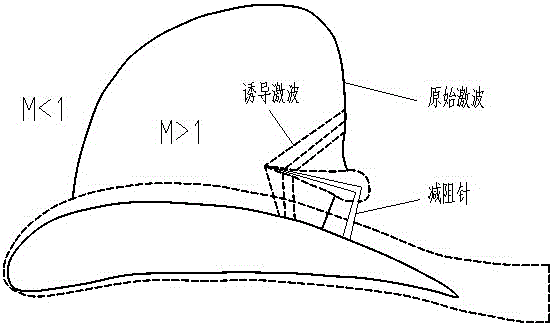
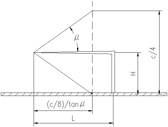
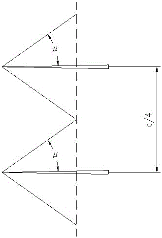
[0025] The invention discloses a passive control device for drag-reducing pins used for wing shock wave control, which specifically includes aircraft wings and drag-reducing pins arranged on the aircraft wings; the drag-reducing pins are fixed on the aircraft wings The shock wave area on the surface, the drag reducing pin is L-shaped, and one end of the drag reducing pin is vertically fixed on the shock wave area on the upper surface of the aircraft wing. The goal of reducing wave drag is achieved by interfering with the initial strong normal shock wave by the drag-reducing needle placed in the shock wave area on the upper surface of the wing, and by generating a series of oblique shock waves to replace the initial normal shock wave.

[0026] The purpose of the present invention is mainly to: propose a kind of transonic wing sho...


PUM


Abstract

Relating to the technical field of shockwave control, the invention discloses a drag reduction needle passive control device for wing shockwave control. The device specifically includes aircraft wings and drag reduction needles arranged on the aircraft wings. The drag reduction needles are fixed in shockwave areas on the upper surfaces of the aircraft wings, the drag reduction needles are L shaped, and one ends of the drag reduction needles are vertically fixed at the shockwave areas on the upper surfaces of the aircraft wings. Through mutual interference of the drag reduction needles placed at the shockwave areas on the upper surfaces of the aircraft wings and initial strong normal shockwaves, a series of oblique shockwaves are generated to replace the initial normal shockwaves so as to reach the purpose of weakening wave drag.

Description

technical field [0001] The invention relates to the technical field of wing shock wave control, and discloses a drag reducing pin passive control method and device for wing shock wave control. Background technique [0002] The requirements of large aircraft for carrying capacity, long range, long endurance and fast transport capability determine that it must have high lift, high aerodynamic efficiency, high flight speed and low fuel consumption. The lift of the aircraft mainly comes from the wings, low fuel consumption corresponds to low resistance, and aerodynamic efficiency is the product of the flight Mach number and the lift-to-drag ratio. Therefore, modern advanced large aircraft require advanced wing technology with small resistance, high cruise lift-to-drag ratio (ratio of lift to drag), and high cruise aerodynamic efficiency. Supercritical wing technology is a wing technology commonly used and applied in modern large aircraft. [0003] The force of the air against ...

Claims


Application Information

Patent Timeline
Patent Type & Authority Applications(China)
IPC IPC(8): B64C1/38
CPCB64C1/38
Inventor 陶洋罗新福赵忠良范长海刘志勇熊能刘俊刘凯
Owner INST OF HIGH SPEED AERODYNAMICS OF CHINA AERODYNAMICS RES & DEV CENT
Why Eureka
Try Eureka