Supercharge Your Innovation With Domain-Expert AI Agents!

Elastic self-sealing three-eccentric center butterfly valve

A triple-eccentric butterfly valve, self-sealing technology, applied in shaft sealing, lift valve, valve details, etc., can solve the problem of inability to adjust the sealing reliability by itself, and achieve the purpose of eliminating the assembly room, improving the high temperature resistance performance and improving the sealing reliability. Effect

Inactive Publication Date: 2016-09-14
JIANGSU ZHONGHAO MARINE VALVE MFG
View PDF10 Cites 0 Cited by
  • Summary
  • Abstract
  • Description
  • Claims
  • Application Information

AI Technical Summary

Problems solved by technology

The existing triple eccentric butterfly valve has a shaft seal structure at the joint between the upper part of the valve body and the valve stem. This structure is to provide a sealing ring in the ring groove at the joint between the upper part of the valve body and the valve stem on the upper part of the upper bearing. The end of the upper pressure sleeve extends into the ring groove where the upper part of the valve body above the upper bearing and the valve stem are combined to press against the sealing ring to achieve sealing. The defect is that the pressure sleeve is fixedly connected to the upper part of the valve body, and the gap between the sealing ring and the valve stem When there is a large gap due to wear and tear, it cannot be adjusted by itself to ensure the reliability of the seal

Method used


Image

  • Elastic self-sealing three-eccentric center butterfly valve

Examples


Embodiment Construction

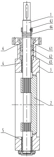
[0017] The present invention will be further described below according to the accompanying drawings and in conjunction with the embodiments.

[0018] The elastic self-sealing triple eccentric butterfly valve shown in the accompanying drawings includes a valve stem 1, a valve plate 2 and a valve body 3; the valve stem 1 is supported on the valve body 3 through the upper bearing 4 and the lower bearing 5 arranged up and down; the valve stem 1, The valve plate 2 is connected by a spline structure; a shaft seal structure 6 is provided at the joint between the upper part of the valve body 3 and the valve stem 1; the shaft seal structure 6 includes a gasket 6.5 and a graphite filler 6.2 which are sequentially fitted on the valve stem 1 from the upper end of the valve stem 1 , pressure sleeve 6.1, pressure ring 6.3; pressure sleeve 6.1 is slidingly matched with the ring groove at the junction of the valve body 3 upper part on the upper part of the upper bearing 4 and the valve stem 1,...


PUM


Abstract

The invention discloses an elastic self-sealing three-eccentric center butterfly valve. The valve comprises a valve rod, a valve plate and a valve body; the valve rod is borne on the valve body through an upper bearing and a lower bearing which are arranged up and down, and a shaft seal structure is arranged at the combining position of the upper portion of the valve body and the valve rod and comprises graphite packing, a pressing sleeve and a pressing ring which are sequentially arranged on the valve rod in a sleeving manner from the upper end of the valve rod; the pressing sleeve enables the graphite packing to be closed in a ring groove in the position, where the upper portion of the upper bearing is combined with the valve rod, of the upper portion of the valve body; the pressing ring is fixedly connected with the valve rod, and a compression spring arranged on the valve rod in a sleeving manner is arranged between the lower end face of the pressing ring and the upper end face of the pressing sleeve; and according to the further improvement, a gasket ring arranged on the valve rod in a sleeving manner is arranged on the lower portion of the graphite packing in the ring groove in the position, where the upper portion of the upper bearing is combined with the valve rod, of the upper portion of the valve body; the contact end face of the pressing sleeve and the graphite packing and the contact end face of the gasket ring and the graphite packing are conical faces, the large ends of the conical faces face the graphite packing, and the valve rod and the valve plate are connected through a spline structure; and elastic self sealing can be achieved, the leakage amount of the valve is small, and sealing is reliable.

Description

technical field [0001] The invention relates to a valve, in particular to a triple eccentric butterfly valve. Background technique [0002] The triple eccentric butterfly valve is a butterfly valve in which the shaft center of the valve stem deviates from the center of the valve disc and the center of the valve body at the same time, and the sealing pair is an oblique cone. Triple eccentric butterfly valves are widely used in industrial pipelines such as metallurgy, electric power, petrochemical industry, water supply and drainage, and municipal construction to regulate flow and cut off fluid. The existing triple eccentric butterfly valve has a shaft seal structure at the joint between the upper part of the valve body and the valve stem. This structure is to provide a sealing ring in the ring groove at the joint between the upper part of the valve body and the valve stem on the upper part of the upper bearing. The end of the upper pressure sleeve extends into the ring groov...

Claims


Application Information

Patent Timeline
IPC IPC(8): F16K41/06F16K41/02F16K1/22F16K1/48
CPCF16K41/063F16K1/2268F16K1/48F16K41/023
Inventor 全文章李顺明
Owner JIANGSU ZHONGHAO MARINE VALVE MFG
Features
  • R&D
  • Intellectual Property
  • Life Sciences
  • Materials
  • Tech Scout
  • Unparalleled Data Quality
  • Higher Quality Content
  • 60% Fewer Hallucinations
Learn More