Air-liquid separator group for refrigerating system

A gas-liquid separator and refrigeration system technology, applied in refrigeration components, refrigeration and liquefaction, refrigerators, etc., can solve problems such as compressor liquid shock, compressor damage, unreasonable design of the gas-liquid separator group, etc., to achieve flow The effect of good distance and prolonging service life

Inactive Publication Date: 2016-09-14
HEFEI CARNOT AUTOMOTIVE AIR CONDITIONING
View PDF5 Cites 7 Cited by
  • Summary
  • Abstract
  • Description
  • Claims
  • Application Information

AI Technical Summary

Problems solved by technology

In the prior art, due to the unreasonable design of the gas-liquid separator group, the liquid refrigerant that has not been evaporated in the evaporator directly flows back into the compressor when it enters the gas-liquid separator, resulting in liquid shock of the compressor.
In addition, the gas-liquid separator group in the prior art does not have the filtering function, and various impurities generated after the long-term operation of the refrigeration system will directly flow back into the compressor through the gas-liquid separator, causing compression machine damage

Method used


Image

  • Air-liquid separator group for refrigerating system
  • Air-liquid separator group for refrigerating system
  • Air-liquid separator group for refrigerating system

Examples


Embodiment Construction

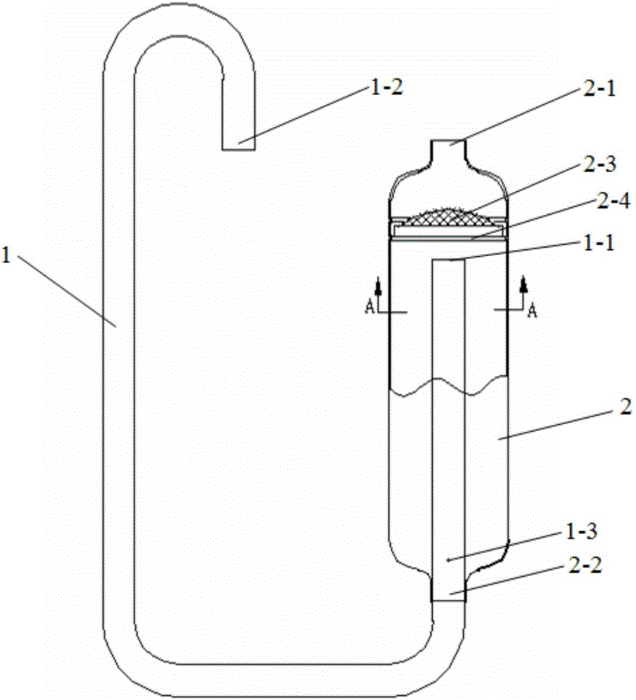
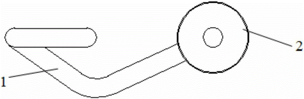
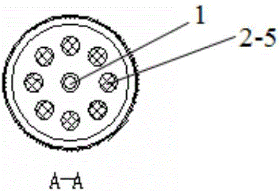
[0017] See attached Figure 1-Figure 3 As shown, a gas-liquid separator group for a refrigeration system is composed of a liquid storage tank 2 and a gas return pipe 1. The liquid storage tank 2 is a hollow cylinder with an upper port 2-1 and a lower port 2-2. , a filter screen 2-3 is provided at a distance of 50cm ± 5cm from the upper port 2-1, and a liquid separation baffle 2-4 is provided at the lower end of the filter screen 2-3; the shape of the return air pipe 1 is U-shaped circular pipe, which has an air inlet port 1-1 and an air return port 1-2, the air inlet port 1-1 is inserted into the liquid storage tank 2 and connected to the liquid separation baffle 2-4 There is a distance of 10-15mm between them, and an oil return hole 1-3 is provided on the air return pipe 1 inserted into the liquid storage tank 2 .

[0018] Preferably, the filter screen 2-3 is 60 mesh.

[0019] Preferably, the filter screen 2-3 is made of 1Cr18Ni9Ti.

[0020] Preferably, the liquid separati...


PUM


Abstract

The invention relates to an air-liquid separator, in particular to an air-liquid separator group for a refrigerating system. The air-liquid separator group for the refrigerating system is formed by a liquid storage tank and an air return pipe. The liquid storage tank is a hollow cylinder body with an upper port and a lower port; a filter screen is arranged on a part, which is 50+ / -5cm far away from the upper port; a liquid separation baffle plate is arranged on the lower end of the filter screen; the air return pipe is a circular pipe with a U-shaped structure and is provided with an air inlet port and an air return port; the air inlet port is inserted into the liquid storage tank; a gap with the distance of 10 to 15mm is formed between the liquid storage tank and the liquid separation baffle plate; oil return holes are formed on the air return pipe inserted into the liquid storage tank. According to the air-liquid separator group for the refrigerating system provided by the invention, the air return pipe with the U-shaped structure and liquid separation holes arrayed according to an equiangular circumference array are adopted, so that the phenomenon that a compressor is damaged since a liquid-state refrigerating fluid directly enters the air return pipe can be effectively avoided; besides, the filter screen is designed on the upper end of the liquid storage tank, and the refrigerating fluid returned through an evaporator is firstly filtered through the filter screen, and then enters the compressor through the air return pipe.

Description

technical field [0001] The invention relates to a gas-liquid separator, in particular to a gas-liquid separator group for a refrigeration system. Background technique [0002] The gas-liquid separator group used in the refrigeration system is mainly installed between the evaporator and the compressor. Its main function is to separate the gaseous and liquid refrigerants, so that the refrigerants enter the compressor from the suction port of the compressor in the form of gas, to prevent liquid shock to the compressor, and at the same time return the refrigerated oil to the compressor to lubricate the compressor , to ensure the normal operation of the compressor and store part of the liquid refrigerant. In the prior art, due to the unreasonable design of the gas-liquid separator group, the unevaporated liquid refrigerant in the evaporator directly flows back into the compressor when it enters the gas-liquid separator, resulting in liquid shock of the compressor. In addition, ...

Claims


Application Information

Patent Timeline
Patent Type & Authority Applications(China)
IPC IPC(8): F25B43/00F25B43/02
CPCF25B43/006F25B43/003F25B43/02F25B2400/23
Inventor 吴建辉
Owner HEFEI CARNOT AUTOMOTIVE AIR CONDITIONING
Why Eureka
Try Eureka