Conveying plate for large area panel

A conveying plate, large-size technology, applied in the field of conveying plates, can solve the problems of poor process, unsuitable manufacturing from an economic point of view, and difficult processing of scroll pins, and achieves the advantages of suppressing local sagging, good suspension flatness, and reducing jitter. Effect

Active Publication Date: 2013-10-30
デフンハイテク株式会社
View PDF9 Cites 5 Cited by
  • Summary
  • Abstract
  • Description
  • Claims
  • Application Information

AI Technical Summary

Problems solved by technology

[0014] However, the non-contact conveying plate proposed by the applicant is formed by clamping the scroll pin forming the spiral groove into the air inlet, but the processing of the scroll pin is too difficult, the productivity is low, and the assembly also requires High precision cannot reach the level of mass production, and the manufacturing cost is also high
[0015] In addition, various panels such as display panels and solar panels are gradually becoming larger, and it is more difficult to transfer them stably while maintaining flatness. image 3 As shown, as the size of the display panel gradually increases, the drooping phenomenon of the left and right side edges along the transfer direction gradually becomes serious, which leads to problems such as poor workmanship
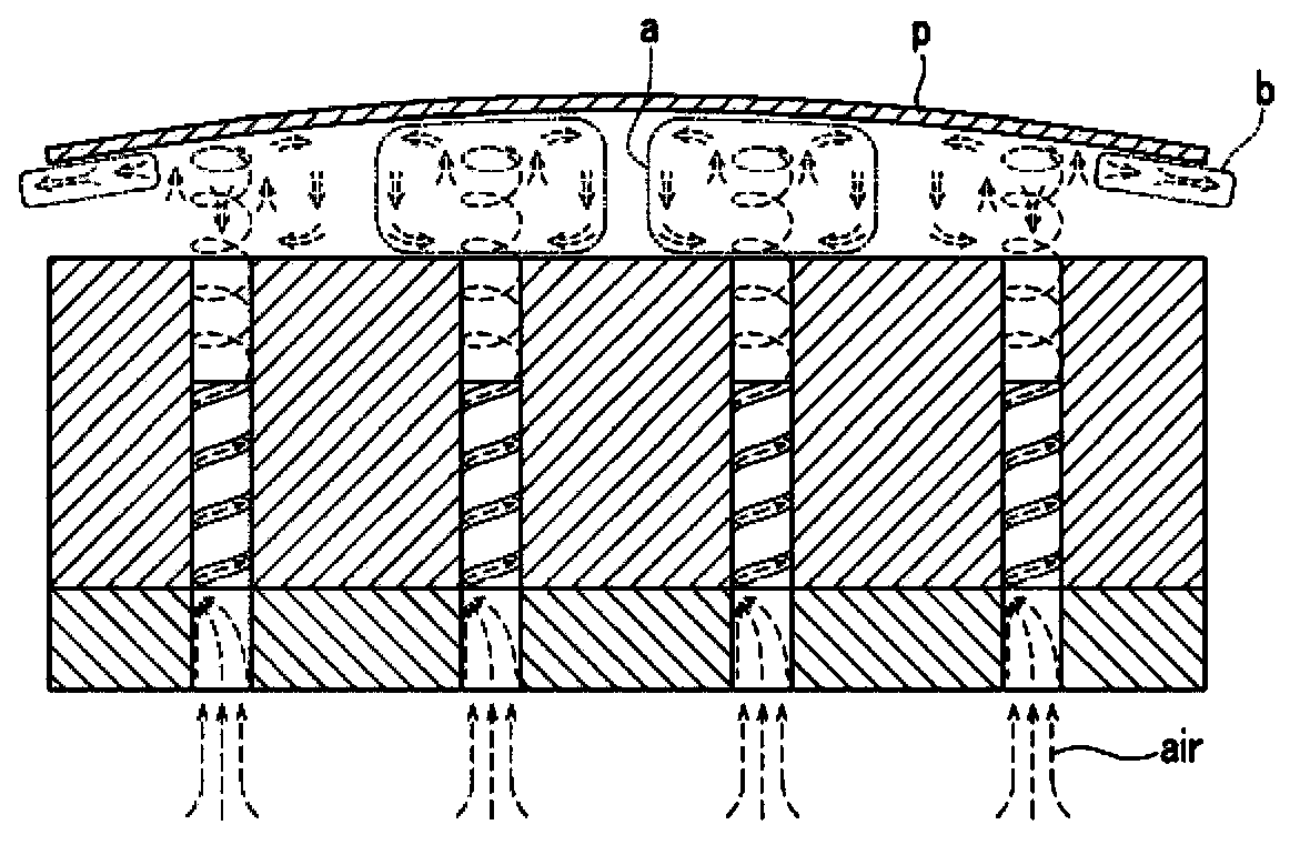
[0016] That is, according to image 3 , the air pressure ejected from the air hole located on the lower center side of the conveyed body (p) cannot be discharged to the outside, forming a stagnant stagnant airflow (a), ejected from the air hole located on the edge side of the conveyed object (p) The air pressure is in the state of being in contact with the outside air, and the ejected air cannot flow to the staying airflow (a), forming an exhaust airflow (b) that is quickly discharged to the outside, and finally causes the conveyed body (p) to be transported as shown in the figure Problems with poor flatness such as protrusion of the central part shown
[0017] Solar panels, which have recently attracted attention as an environmentally friendly energy source, are large in size and difficult to control flatness under local loads due to the process of transporting heavy glass substrates (Borosilicate and Sodalime series) for vapor deposition and other processes, and ultimately cannot realize large-scale Production, and low transportability, economically unsuitable for manufacturing

Method used


Image

  • Conveying plate for large area panel
  • Conveying plate for large area panel
  • Conveying plate for large area panel

Examples


Embodiment Construction

[0064] The preferred embodiments of the invention will be described in detail below with reference to the accompanying drawings. The description content and the actual same component in each drawing are indicated by the same symbol, and the description will not be repeated. Furthermore, when describing the present invention, if a specific description of a known function or structure obscures the gist of the present invention, the description will be omitted.

[0065] Figure 4 It is a perspective view of a conveyor plate for large-sized panels according to an embodiment of the present invention. In the figure, an air branch plate with a thin metal plate is interposed in the middle, and an upper plate with a plurality of air holes 33 is arranged on the upper side. The lower side of the air branch plate 20 shows a large-sized panel with a structurally configured lower plate 10. plate 1.

[0066] Figure 5 It is an exploded perspective view of a conveyor plate for large-sized...


PUM


Abstract

PURPOSE: A noncontact conveying plate for a large area panel is provided to minimize the generation of tremor due to vibration generating while transferring a target object, and to properly maintain the floated flatness of the target object. CONSTITUTION: A noncontact conveying plate for a large area panel comprises a lower plate(10), an upper plate(30), a vacuum branch plate, and an air branch plate(20). The lower plate comprises an air port(a1) and a vacuum port through which air and vacuum pressure are respectively supplied from the outside. The lower plate is connected to the vacuum port at the top to form a vacuum chamber. The upper plate comprises an air chamber, air holes, and vacuum holes. The vacuum branch plate is arranged between the lower plate and the upper plate and is connected to the vacuum chamber to form a vacuum load for delivering the vacuum pressure to the vacuum holes. The air branch plate is arranged at the top or the bottom of the vacuum chamber.

Description

technical field [0001] The present invention relates to a conveying board that uses the buoyancy of the air to transfer various display panels and large-sized thin plates in a non-contact manner. Specifically, when transporting large-sized panels, it can suppress shaking, improve stability during transfer, and suppress edges. A conveyor plate for large-sized panels that maintains flatness due to sagging. Background technique [0002] In-Line FPD Automatic Optical Inspection (In-Line FPD Automatic Optical Inspection) refers to guide the TFT LCD panel or PDP, color filter and other display panels (display panel) to use the optical lens and CCD camera to capture images at the same time, and then apply the image processing algorithm to detect Users need to find out the various defects of the equipment. [0003] The online inspection equipment is roughly divided into a scan section for detecting defects, a review section, and an unlaod section. In order for the inspection equip...

Claims


Application Information

Patent Timeline
Patent Type & Authority Applications(China)
IPC IPC(8): B65G51/02
CPCB65G47/911B65G49/065B65G51/03B65G2249/045G02F1/1303H01L21/67784
Inventor 李在成
Owner デフンハイテク株式会社
Why Eureka
Try Eureka