Optical fiber preform and manufacturing method of optical fiber

A technology of optical fiber preform and equipment, which is applied in the field of low-loss optical fiber preparation, can solve the problems of optical fiber background loss, uneven distribution of core refractive index, and small core diameter of optical fiber preform, so as to reduce loss and reduce clusters” effect of effect

Inactive Publication Date: 2019-02-01
XI'AN INST OF OPTICS & FINE MECHANICS - CHINESE ACAD OF SCI
View PDF4 Cites 6 Cited by
  • Summary
  • Abstract
  • Description
  • Claims
  • Application Information

AI Technical Summary

Problems solved by technology

[0005] Aiming at the technical problems of small core diameter of the optical fiber preform prepared by the existing method, uneven distribution of the core refractive index in the optical fiber preform, and large background loss of the optical fiber, the present invention provides a method for preparing an optical fiber preform and using the method The prepared optical fiber preform is prepared by the method of preparing optical fiber, which adopts the improved chemical vapor deposition (MCVD) combined with the rare earth ion gas phase doping method. The core diameter of the prepared preform is larger than 3mm, the refractive index distribution is relatively uniform, and the preparation process is simple. Yield per preform

Method used


Image

  • Optical fiber preform and manufacturing method of optical fiber
  • Optical fiber preform and manufacturing method of optical fiber
  • Optical fiber preform and manufacturing method of optical fiber

Examples


Embodiment 1

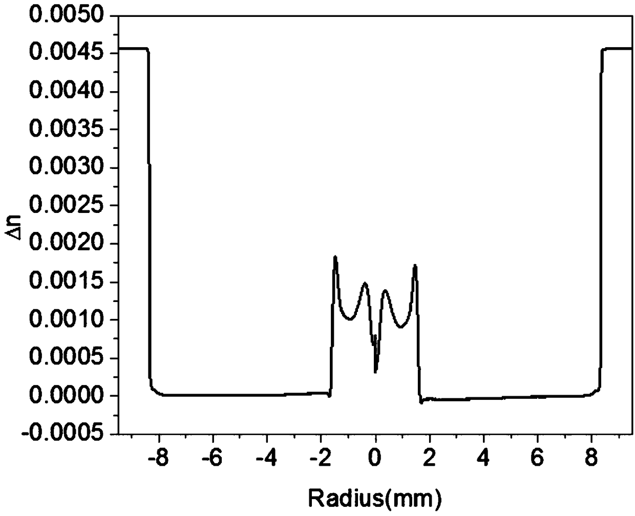
[0058] According to Table 1, the flow rate of each component in each deposition layer is set in the MCVD automatic control software; the quartz tube is connected to the MCVD deposition lathe, and the quartz tube is preheated by the hydrogen-oxygen flame. After the preheating is completed, the SF 6 The gas erodes the inner wall of the quartz tube; after the erosion, the gas material is passed into the quartz tube to start depositing the core layer; The speed is 100mm / min; after the deposition is finished, 5sccm of Cl is introduced 2 Shrunk the quartz tube, after the hollow tube has been shrunk many times and fired into a solid rod, the prefabricated rod was flame-polished at 1600°C, and its refractive index and rod core diameter were tested. The results are as follows: figure 1 and 1 in Table 6 # sample shown, from figure 1 It can be seen that the radial refractive index distribution of the optical fiber preform is not uniform, and it is difficult to meet the requirements of ...

Embodiment 2

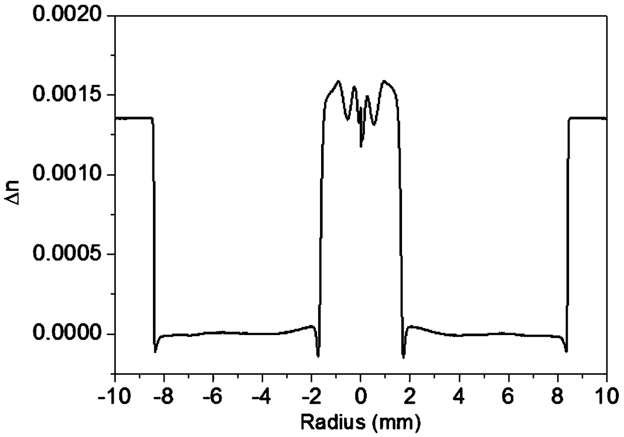
[0062] According to the component flow rate and refractive index distribution diagram of the prefabricated rod in Experimental Example 1, adjust the component Al(acac) in the deposited layer 3 and SiF 4 The flow rate, see Table 2, set the component flow rate in the MCVD automatic control software; connect the quartz tube to the MCVD deposition lathe, preheat the quartz tube through the hydrogen-oxygen flame, and pass it into SF after the preheating is completed 6 The gas erodes the inner wall of the quartz tube; after the erosion, the gas material is passed into the quartz tube to start depositing the core layer; The speed is 100mm / min; after the deposition is finished, 5sccm of Cl is introduced 2 Shrink the quartz tube, and after the hollow tube has been shrunk several times and fired into a solid rod, the optical fiber preform is polished with flame at 1600°C. Test the refractive index of the optical fiber preform and calculate the corresponding numerical aperture, the res...

Embodiment 3

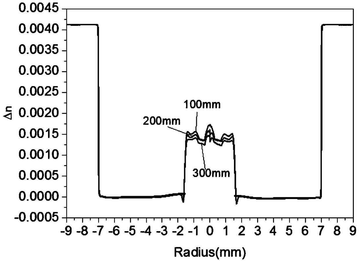
[0067] Adjust the reaction material Al(acac) in the deposition layer according to the component flow rate and the refractive index distribution diagram of the prefabricated rod in Experimental Example 1 3 and SiF 4 The flow rate, see Table 3, set the component flow rate in the MCVD automatic control software; connect the quartz tube to the MCVD deposition lathe, preheat the quartz tube through the hydrogen-oxygen flame, and pass the SF after the preheating is completed. 6 The gas erodes the inner wall of the quartz tube; after the erosion, the gas material is passed into the quartz tube to start depositing the core layer; The speed is 100mm / min; after the deposition is finished, 5sccm of Cl is introduced 2 Shrink the quartz tube, and after the hollow tube has been shrunk several times and fired into a solid rod, the optical fiber preform is polished with flame at 1600°C. Test the refractive index of the optical fiber preform of this embodiment, the results are shown in ima...


PUM

PropertyMeasurementUnit
diameteraaaaaaaaaa
diameteraaaaaaaaaa

Abstract

The invention relates to an optical fiber preform and a manufacturing method of an optical fiber, in particular to a manufacturing method of the optical fiber preform with a large core diameter and acorresponding low loss optical fiber, the method solves the problem of the optical fiber preform with a small core diameter prepared in the prior art. The manufacturing method of the optical fiber preform includes, adopting an improved chemical vapor deposition (MCVD) combined with a rare earth ion gas phase doping method; depositing all materials under a gas phase condition; and then obtaining the optical fiber preform with a large core diameter through sintering and tube shrinkage processes, wherein components of the manufactured optical fiber preform core are SiO2, Al2O3, Yb2O3, Ce2O3 and F, the diameter of the preform core > 3 mm. The manufacturing method of the optical fiber includes, selecting an appropriate sleeve process to sleeve the manufactured optical fiber preform to enable the core-to-package ratio to meet the requirements of the optical fiber; processing the sleeved preform into an octagonal structure; and performing wire drawing at a temperature of 2050 + / -20 DEG C to draw into the optical fiber.

Description

technical field [0001] The invention relates to a method for preparing an optical fiber preform and an optical fiber, in particular to a method for preparing a large core-diameter optical fiber preform and a corresponding low-loss optical fiber. Background technique [0002] Fiber lasers are called the third-generation lasers. Compared with traditional lasers, fiber lasers have many advantages, such as high electro-optical conversion efficiency, good beam quality, long service life, strong environmental adaptability, and small footprint. They are energy-saving and environmentally friendly. Optoelectronic devices have been widely used in industrial manufacturing, medical treatment, energy exploration, military defense and other fields, and the growth rate of their market sales has reached double digits for several consecutive years. [0003] As the core device of high-power fiber lasers, laser fiber materials are the key factors that determine the power of fiber lasers, and e...

Claims


Application Information

Patent Timeline
Patent Type & Authority Applications(China)
IPC IPC(8): C03C13/04C03B37/018C03B37/027
CPCC03B37/01807C03B37/027C03C13/045
Inventor 侯超奇折胜飞李玮楠常畅赵保银郑锦坤李哲高菘张岩
Owner XI'AN INST OF OPTICS & FINE MECHANICS - CHINESE ACAD OF SCI
Why Eureka
Try Eureka