
Method and plant for integrated monitoring and control of strip flatness and strip profile

a technology of flatness and strip profile, applied in the direction of profile control device, measuring device, manufacturing tool, etc., can solve the problems of partial flatness measurement, difficult direct contact measurement of strip flatness or tension stress profile, and different flatness or tension profile, etc., to inhibit strip buckling

Active Publication Date: 2010-12-14
NUCOR CORP
View PDF45 Cites 6 Cited by
  • Summary
  • Abstract
  • Description
  • Claims
  • Application Information

AI Technical Summary

Benefits of technology

The patent text describes a method for controlling the geometry of thin steel strip as it passes through a hot rolling mill. The method involves measuring the thickness profile of the incoming strip before it enters the hot rolling mill and calculating a target thickness profile based on the measured profile and flatness requirements. The method also involves measuring the thickness profile of the strip after it exits the hot rolling mill and using this information to control the geometry of the strip as it passes through the hot rolling mill. The technical effect of this method is to improve the quality and control of the hot rolling process, resulting in better flatness and tension control of the thin steel strip.

Problems solved by technology

The “measured” strip flatness and tension profile as measured at a device downstream of the hot rolling mill are insufficient to control in practice the hot rolling mill because, unlike cold mills (where the measured downstream flatness or tension profile of the strip closely resembles the flatness or tension profile produced off the mill), the flatness or tension profile may differ due to the action of creep.
The high strip temperature at the exit of steel hot mills also makes difficult the measurement of the strip flatness or tension stress profile by direct contact.
However, such non-contact flatness measurement results in partial flatness measurement, since at any given time only part of the strip exhibits measured flatness defects.
In addition, creep in the strip results in the flatness of the strip at the roll stand exit likely being significantly worse than that measured downstream at practical flatness gauge locations.
The strip entry temperature to the hot mill is higher than found in the final stand of the typical hot mill, approximately 1100° C. A consequence of thin strip high temperature and casting process is that the strip entry tension is low, and therefore is more susceptible to buckling and creep prior to entry into the hot mill.
Low tensions employed in hot rolling mills results in small local roll-gap errors and loss of tension stress at points across the strip width, and results in strip buckles and poor strip flatness.

Method used


Image

  • Method and plant for integrated monitoring and control of strip flatness and strip profile
  • Method and plant for integrated monitoring and control of strip flatness and strip profile
  • Method and plant for integrated monitoring and control of strip flatness and strip profile

Examples


Embodiment Construction

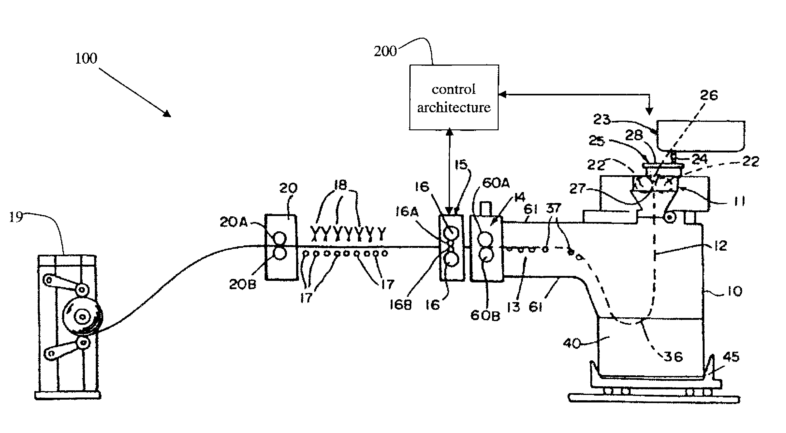
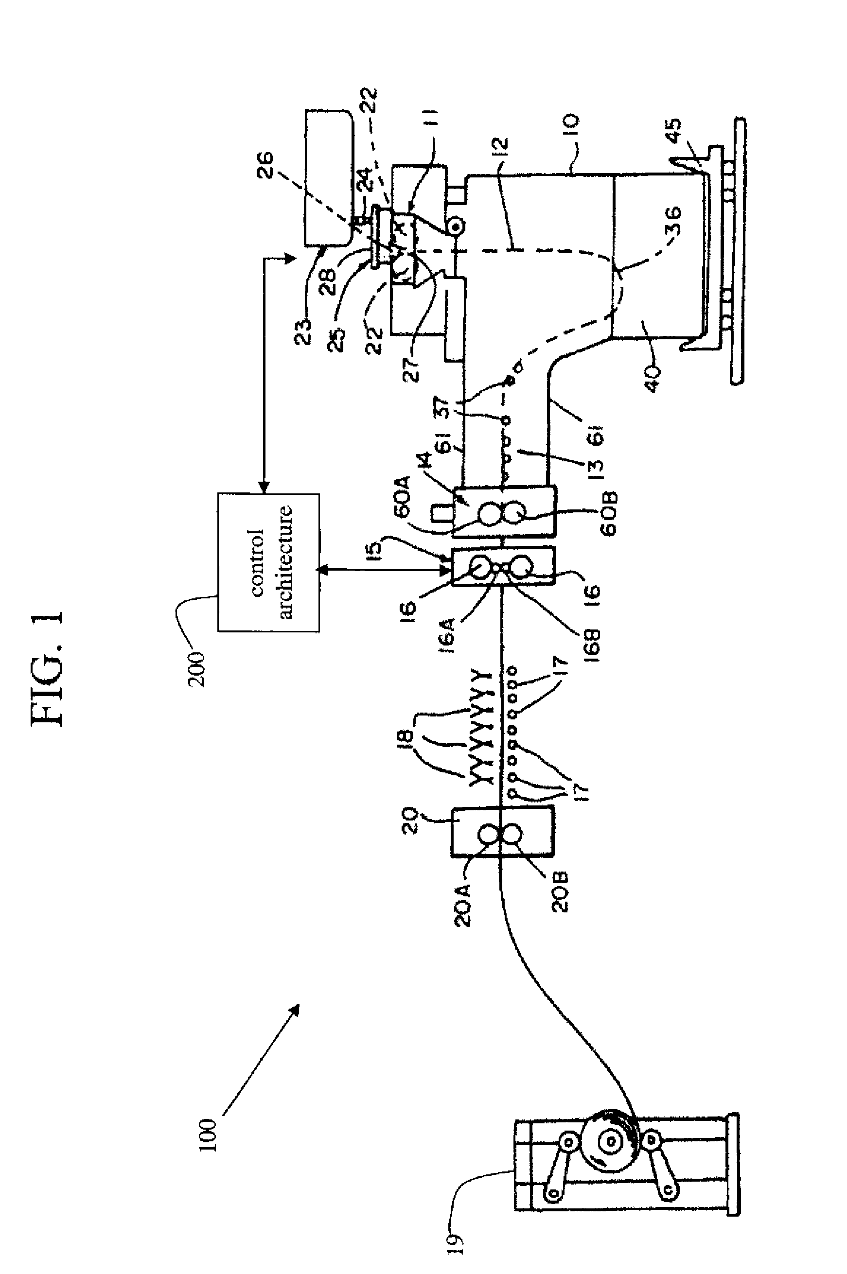
[0057]FIG. 1 is a schematic drawing illustrating a thin strip casting plant 100 having a rolling mill 15 and a control architecture 200. The illustrated casting and rolling installation comprises a twin-roll caster, denoted generally by 11, which produces thin cast steel strip 12 and comprises casting rolls 22 and side dams 26. During operation, the casting rolls are counter-rotated by a drive (not shown). A metal delivery system comprising at least a moveable tundish 23, a large tundish 25, and a core nozzle 24 provides molten steel to the twin roll caster 11. Thin cast steel strip 12 passes downwardly through a nip 27 between the casting rolls 22 and then into a transient path across a guide table 13 to a pinch roll stand 14. After exiting the pinch roll stand 14, thin cast strip 12 passes into and through hot rolling mill 15 comprised of back up rolls 16 and upper and lower work rolls 16A and 16B, where the geometry (e.g., thickness, profile, and / or flatness) of the strip may be ...


PUM

PropertyMeasurementUnit
thicknessaaaaaaaaaa
thicknessaaaaaaaaaa
thicknessaaaaaaaaaa

Abstract

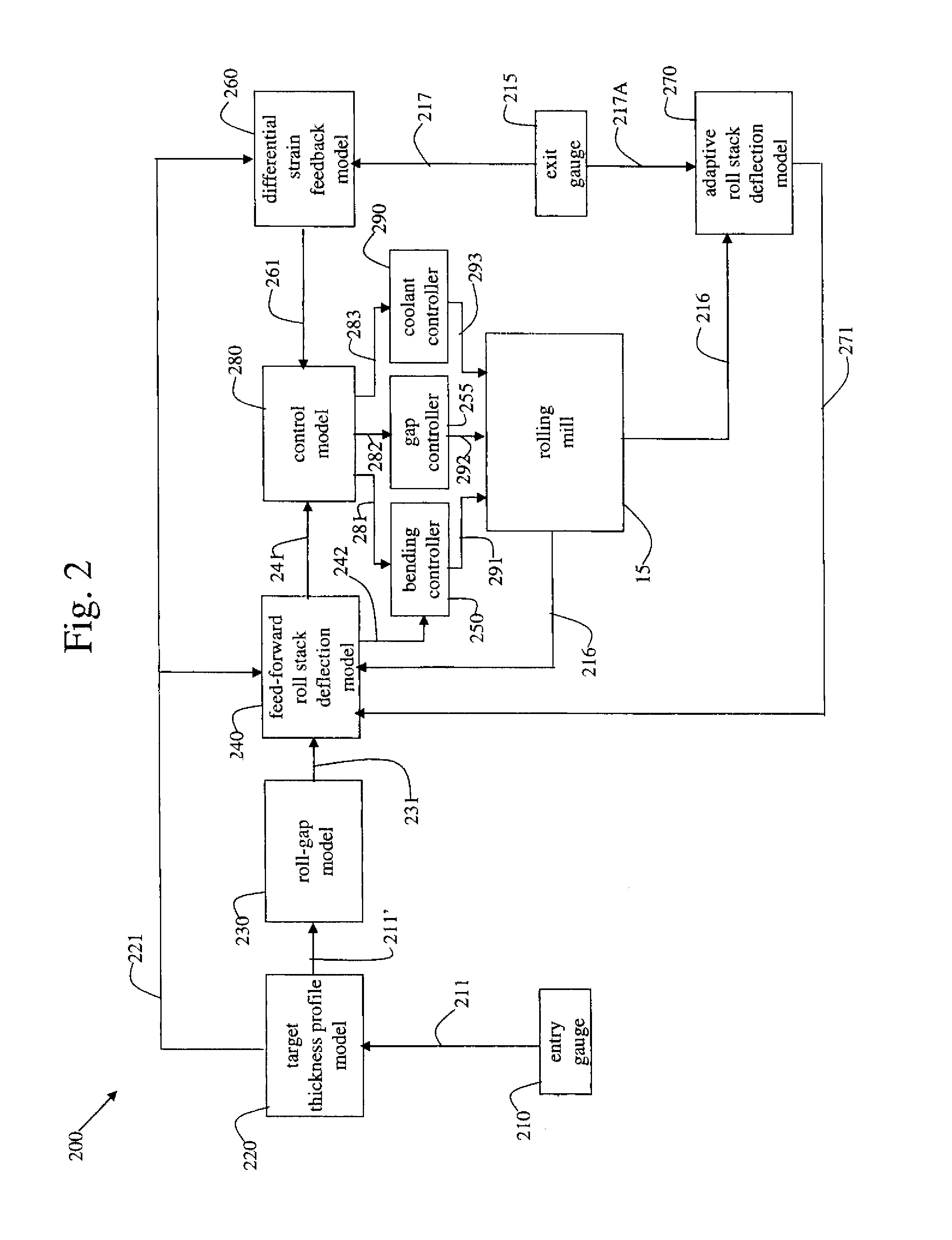
Apparatus and method of controlling strip geometry in casting strip having a rolling mill. A target thickness profile is calculated as a function of the measured entry thickness profile of the strip while satisfying profile and flatness operating requirements. A differential strain feedback from longitudinal strain in the strip is calculated by a control system by comparing the exit thickness profile with the target thickness profile, and a control signal is generated to control a device capable of affecting the geometry of the strip processed by the hot rolling mill. A feed-forward control reference and / or sensitivity vector may also be calculated as a function of the target thickness profile, and used in generating the control signal sent to the control device. The control device may be selected from one or more of the group consisting of a bending controller, gap controller and coolant controller.

Description

CROSS-REFERENCE TO RELATED APPLICATIONS[0001]This patent application claims priority to and the benefit of U.S. Provisional Patent Application Ser. No. 60 / 780,326 which was filed on Mar. 8, 2006, and is incorporated herein by reference in its entirety.BACKGROUND AND SUMMARY OF THE INVENTION[0002]In continuous casting of thin steel strip, molten metal is cast directly by casting rolls into thin strip. The shape of the thin cast strip is determined by, among other things, the surface of the casting surfaces of the casting rolls.[0003]In a twin roll caster, molten metal is introduced between a pair of counter-rotated laterally positioned casting rolls which are internally cooled, so that metal shells solidify on the moving casting roll surfaces and are brought together at the nip between the casting rolls to produce a thin cast strip product. The term “nip” is used herein to refer to the general region at which the casting rolls are closest together. The molten metal may be poured from...

Claims


Application Information

Patent Timeline
Patent Type & Authority Patents(United States)
IPC IPC(8): B21B37/00B21B37/58
CPCB21B37/28B21B1/463B21B13/22B21B37/32B21B37/38B21B37/44B21B38/02B21B45/0218B21B2015/0057B21B2263/02B21B37/16
Inventor BRITANIK, RICHARDDOMANTI, TINOGERBER, TERRY L.MUELLER, JASON A.WALLACE, GLENREES, HAROLD BRADLEY
Owner NUCOR CORP
Learn More