Metallurgical boiler tail gas purification treatment device

A tail gas purification and treatment device technology, applied in the direction of climate sustainability, reduction of greenhouse gases, chemical instruments and methods, etc., can solve the problems of short contact time between flue gas and liquid, insufficient contact with liquid, residual harmful gas, etc. Achieve better absorption effect, less water content, and avoid secondary pollution

Inactive Publication Date: 2018-11-06
安徽申泉化工有限公司
View PDF8 Cites 5 Cited by
  • Summary
  • Abstract
  • Description
  • Claims
  • Application Information

AI Technical Summary

Problems solved by technology

[0002] Metallurgical technologies mainly include pyrometallurgy, hydrometallurgy and electrometallurgy. Metallurgical furnaces are often used in pyrometallurgy. The fuel for metallurgical furnaces is coal. During the combustion process of metallurgical furnaces, a large amount of flue gas is produced. Pollutants include soot (fly ash), acid gas, heavy metals and dioxins, etc. Therefore, it is necessary to treat the flue gas so that it can be discharged into the air after reaching the standard, and the existing tail gas treatment is often through dust collectors and Spray alkaline liquid for separation and absorption. However, due to the strong fluidity of the gas, the contact time between the flue gas and the liquid is short, and the acid gas in the flue gas cannot fully contact with the liquid within a limited time, resulting in Harmful gases still remain in the flue gas, making the treatment incomplete

Method used


Image

  • Metallurgical boiler tail gas purification treatment device
  • Metallurgical boiler tail gas purification treatment device
  • Metallurgical boiler tail gas purification treatment device

Examples


Embodiment Construction

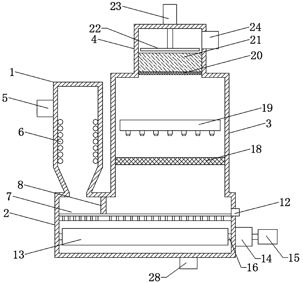
[0019] Please refer to the figure, in the embodiment of the present invention, a metallurgical boiler tail gas purification treatment device includes a heat exchange box 1, a contact box 2, a spray box 3, a dehumidification box 4 and a smoke inlet pipe 5; the heat exchange box 1 and The spray boxes 3 are arranged side by side on the contact box 2, and communicate with the upper sides of the two ends of the contact box 2 respectively; the heat exchange box 1 is connected with a smoke inlet pipe 5, and the boiler flue gas is sent into the heat exchange box 1 A heat exchange tube 6 is coiled on the inner wall of the heat exchange box 1, and flowing cooling water is passed into the heat exchange tube 6 to absorb and take away the heat in the flue gas to reduce the temperature of the flue gas.

[0020] A horizontal spoiler 7 is arranged in the contact box 2, and the spoiler 7 divides the contact box 2 into upper and lower parts, on the upper surface of the spoiler 7 and between the ...


PUM

PropertyMeasurementUnit
thicknessaaaaaaaaaa

Abstract

The invention discloses a metallurgical boiler tail gas purification treatment device. The device comprises a heat exchange box, a contact box, a spraying box, a dehumidifying box and a smoke inlet pipe, the heat exchange box and the spraying box are arranged on the contact box side by side, and are respectively communicated with the upper side and the lower side of the two ends of the contact box, a horizontal spoiler is arranged in the contact box, a plurality of horizontally-parallel flow guide grooves are formed in the upper surface of the spoiler, a plurality of first through holes and second through holes are formed in the bottom of the flow guide groove, a plurality of horizontal rotating rollers are arranged in the corresponding contact box below the spoiler. According to the device, due to the arrangement of the spoiler and the baffle, the flue gas can flow in the preset direction, the internal flowing distance is prolonged, the smoke gas makes contact with the liquid in multiple times during the flowing process, so that impurities in the flue gas can be sufficiently absorbed, harmful substances in the flue gas can be reduced, the purification effect is improved, comparedwith common equipment, the device is better in absorption effect, small in equipment size and convenient to use.

Description

technical field [0001] The invention relates to metallurgical environmental protection equipment, in particular to a metallurgical boiler tail gas purification treatment device. Background technique [0002] Metallurgical technologies mainly include pyrometallurgy, hydrometallurgy and electrometallurgy. Metallurgical furnaces are often used in pyrometallurgy. The fuel for metallurgical furnaces is coal. During the combustion process of metallurgical furnaces, a large amount of flue gas is produced. Pollutants include soot (fly ash), acid gas, heavy metals and dioxins, etc. Therefore, it is necessary to treat the flue gas so that it can be discharged into the air after reaching the standard, and the existing tail gas treatment is often through dust collectors and Spray alkaline liquid for separation and absorption. However, due to the strong fluidity of the gas, the contact time between the flue gas and the liquid is short, and the acid gas in the flue gas cannot fully contac...

Claims


Application Information

Patent Timeline
Patent Type & Authority Applications(China)
IPC IPC(8): F23J15/00F23J15/06F23J15/04F23J15/02B01D53/78B01D53/40B01D53/26B01D47/06
CPCB01D47/06B01D53/263B01D53/40B01D53/78F23J15/006F23J15/022F23J15/04F23J15/06Y02E20/30
Inventor 夏运喜刘莎莎杨明
Owner 安徽申泉化工有限公司
Why Eureka
Try Eureka