Projection type holographic grating backlight structure

A technology of holographic grating and backlight structure, which is applied in the field of LED lighting to achieve the effect of uniformity of brightness, expansion of color gamut, and no loss of light energy

Inactive Publication Date: 2016-09-14
JIANGSU SHENGHUI OPTOELECTRONICS
View PDF5 Cites 14 Cited by
  • Summary
  • Abstract
  • Description
  • Claims
  • Application Information

AI Technical Summary

Problems solved by technology

The light spectrum range of the traditional CCFL light source is relatively large, including many other bands of stray light, so its color gamut is generally only about

Method used


Image

  • Projection type holographic grating backlight structure
  • Projection type holographic grating backlight structure
  • Projection type holographic grating backlight structure

Examples


Embodiment Construction

[0022] The present invention will be further described in detail below in conjunction with the accompanying drawings and specific embodiments.

[0023] In the description of the present invention, it should be understood that terms such as "forward", "backward", "front", "rear", "side", etc. indicating orientation or positional relationship are based on the orientation shown in the drawings Or positional relationship is only for the purpose of describing the present invention or simplifying the description, but does not indicate or imply that the device or component referred to must have a specific orientation, be constructed and operated in a specific orientation, and therefore should not be construed as limiting the protection scope of the present invention.

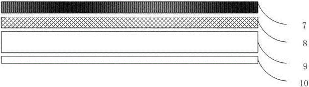
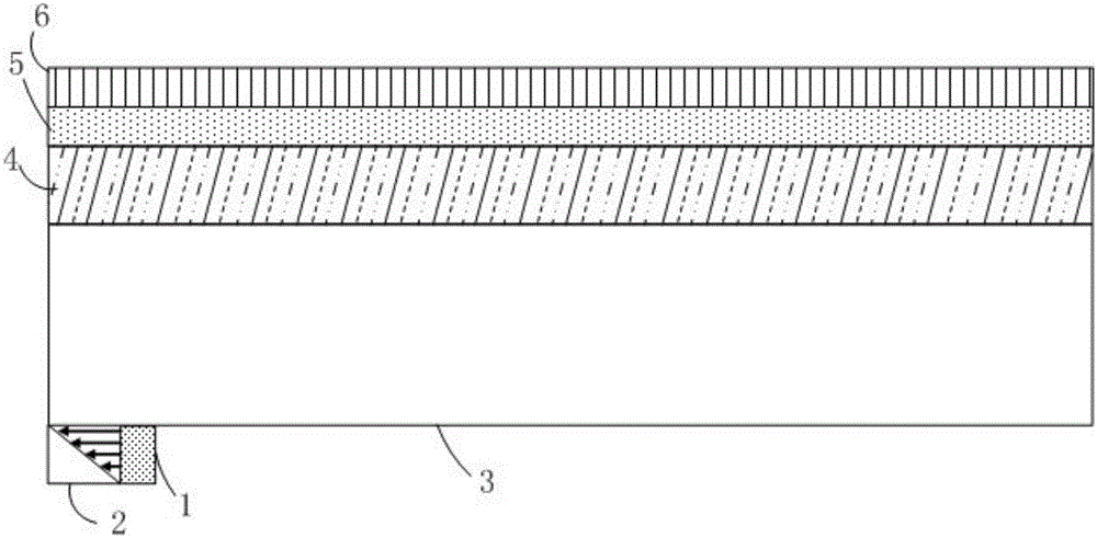
[0024] Such as figure 2 As shown, the composite transmission holographic grating 4 waveguide structure includes a light source 1 , an inclined reflective surface 2 , a flat waveguide layer 3 , a composite transmission...


PUM


Abstract

The present invention relates to a projection type holographic grating backlight structure. The projection type holographic grating backlight structure comprises a light source, an inclined reflection surface, a slab waveguide layer, a complex transmission holographic grating, a liquid crystal layer and a three primary color filter; the light source is positioned at the left lower end of the slab waveguide layer; the inclined reflection surface is positioned at the left side of the light source; the complex transmission holographic grating is positioned at an upper end of the slab waveguide layer; the liquid crystal layer is positioned at an upper end of the complex transmission holographic grating; and the three primary color filter is positioned at an upper end of the liquid crystal layer. According to the lighting structure, the light ray propagation direction of a point light source can be changed, the light is uniformly exported nearly without light energy loss, and luminance uniformity is well achieved. Red, green and blue three-color wave bands in the hybrid light are narrow, monochromaticity is good, so that the displayed color gamut can be expanded, and light efficiency can be improved.

Description

technical field [0001] The invention relates to the technical field of LED lighting, in particular to a preinstalled projection type holographic grating backlight structure. Background technique [0002] At present, the structure of LED backlight module can be divided into side-type and direct-type, but the basic principle is to use the light to be fully reflected in the light guide plate for multiple times to achieve sufficient light mixing, which requires a certain light mixing distance, and it is not easy to achieve thickness. ultra-thin. [0003] At the same time, because the side-lit backlight structure needs to use the backlight panel to convert the LED point light source into a surface light source, and emit the light from the surface, the light will be mixed in the light guide plate and will also cause light loss. The loss of light energy will make the uniformity worse and the brightness darker, and as the size increases, the uniformity will also worsen, so it is di...

Claims


Application Information

Patent Timeline
IPC IPC(8): G02F1/13357G02B6/00
CPCG02F1/133605G02B6/0031G02B6/005G02B6/0065G02F1/133603G02F1/133606G02F1/133611
Inventor 张宇宁张洋沈忠文张祖林
Owner JIANGSU SHENGHUI OPTOELECTRONICS
Why Eureka
Try Eureka