Data transmission method and device of virtual network interface card

A data transmission method and technology of virtual network card, which are applied in the direction of data exchange and network interconnection through path configuration, can solve the problem that the data packets of the virtual network card cannot be transmitted correctly, and achieve low transformation cost, ensure information security, and improve reliability. sexual effect

Active Publication Date: 2016-09-14
HANGZHOU DPTECH TECH
9 Cites 13 Cited by

AI-Extracted Technical Summary

Problems solved by technology

[0004] In view of this, the present application provides a data transmission method and device for a virtual network...

Method used

If the first IP address that client detection gateway distributes for target virtual network card and the IP address of preset network card are in the same network segment, it can be known that the first IP address of target virtual network card will conflict with the IP address of preset network card, this At this time, according to the configured IP addresses of other network cards at present, a second IP address that is not in the same network segment as the IP addresses of all other network cards can be found; specifically, all preset network cards and For the corresponding IP address, when generating the second IP address, it is only necessary to ensure that the second IP address is not in the same network segment as the IP addresses of the above-mentioned other network cards; All IP addresses are not in the second IP address of the same network segment, thereby preventing address conflicts and ensuring th...

Abstract

The invention provides a data transmission method and a data transmission device of a virtual network interface card. The method comprises the steps of acquiring a first IP address distributed to a target virtual network interface card by a gateway; detecting that whether the first IP address is in a same network segment with the IP address of a preset network interface card; when the first IP address is in the same network segment with the IP address of the preset network interface card, configuring a second IP address not in the same network segment with the IP address of the preset network interface card for the target virtual network interface card; and transmitting messages via the target virtual network interface card configured with the second IP address. According to the method, when the first IP address configured to the target virtual network interface card by the gateway is in the same network segment with the IP addresses of the other network interface cards, the second IP address in another different network segment is configured for the target virtual network interface card, so that the IP address conflict problem is avoided, the user information security can be ensured, and the information transmission reliability is improved.

Application Domain

Networks interconnection

Technology Topic

Data transmissionIp address +7

Image

  • Data transmission method and device of virtual network interface card
  • Data transmission method and device of virtual network interface card
  • Data transmission method and device of virtual network interface card

Examples

  • Experimental program(1)

Example Embodiment

[0058] Here, exemplary embodiments will be described in detail, and examples thereof are shown in the accompanying drawings. When the following description refers to the drawings, unless otherwise indicated, the same numbers in different drawings indicate the same or similar elements. The implementation manners described in the following exemplary embodiments do not represent all implementation manners consistent with the present application. Rather, they are merely examples of devices and methods consistent with some aspects of the application as detailed in the appended claims.
[0059] The terms used in the present invention are only for the purpose of describing specific embodiments, and are not intended to limit the application. The singular forms of "a", "said" and "the" used in the present invention and the appended claims are also intended to include plural forms, unless the context clearly indicates other meanings. It should also be understood that the term "and/or" as used herein refers to and includes any or all possible combinations of one or more of the associated listed items.
[0060] It should be understood that although the terms first, second, third, etc. may be used in the present invention to describe various information, the information should not be limited to these terms. These terms are only used to distinguish the same type of information from each other. For example, without departing from the scope of the present invention, the first information may also be referred to as second information, and similarly, the second information may also be referred to as first information. Depending on the context, the word "if" as used herein can be interpreted as "when" or "when" or "in response to determination".
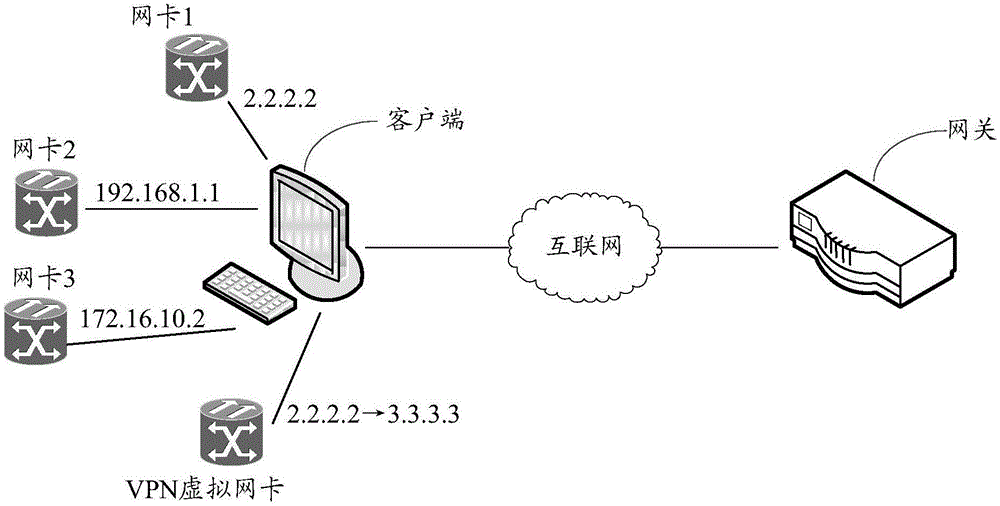
[0061] Such as figure 1 What is shown is a schematic diagram of an application scenario in which an embodiment of the present invention is applied to realize data transmission of a virtual network card. figure 1 Among them, the client can be a mobile terminal and a non-mobile terminal. The non-mobile terminal includes a desktop computer, and the mobile terminal includes a smart phone, a tablet computer, a notebook computer, a personal digital assistant, and the like. The client includes a physical network card, and multiple VPN virtual network cards are set up, and the client can realize data interaction through Internet communication between each virtual network card and the VPN gateway.
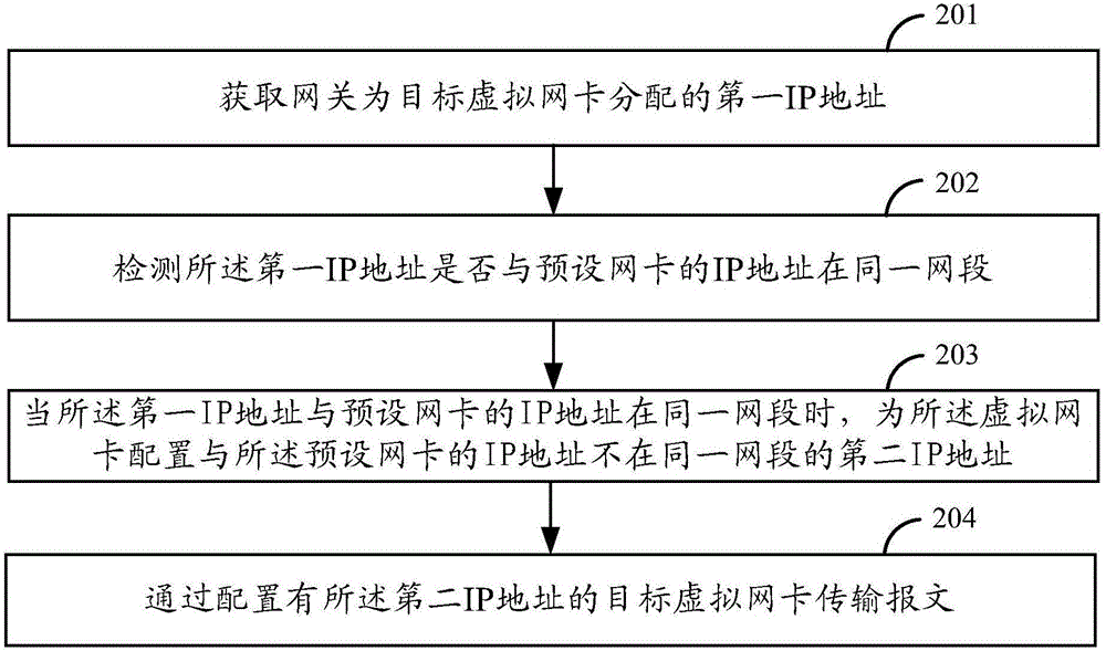
[0062] Such as figure 2 What is described is a schematic flow diagram of an embodiment of the virtual network card data transmission method of the present invention. The method of the embodiment of the present invention can be applied to figure 1 The client includes the following steps:
[0063] In step 201, the first IP address allocated by the gateway to the target virtual network card is obtained.
[0064] Gateway (Gateway) is also called network connector and protocol converter. The gateway realizes network interconnection above the network layer. It is a complex network interconnection device and is only used for the interconnection of two networks with different high-level protocols; the gateway in this embodiment can be a VPN gateway, which is deployed at the boundary of the application server network. The application system that needs to be strengthened is protected by means of open circuit access control, and the user can access the protected application service only through the VPN gateway device.
[0065] Virtual network card, also known as virtual network adapter, uses software to simulate the network environment and simulate network adapter; virtual network card is a feasible network card for the client, but it is not a real physical network card, but a software module running in the client ; Virtual network card is mainly to establish a local area network between remote computers. The virtual network card can simulate the hub function and realize the function of VPN, so that the system recognizes the software as a network card. Through the virtual network card, as long as it can access the external network, it can be connected to the virtual hub to form a local area network with other computers. On this virtual local area network, all physical operations of the local area network can be performed, such as mutual access, exchange of messages, and online games.
[0066] In this step, the VPN gateway device assigns the first IP address to the target virtual network card. The target virtual network card is a network card preset in the client without an IP address. The VPN gateway device can be based on its preset network segment as The network card without an IP address is configured with an IP address and transmitted to the client through the network.
[0067] In step 202, it is detected whether the first IP address and the IP address of the preset network card are in the same network segment.
[0068] Since multiple network cards are preset in the client, the preset network card may include the physical network card of the machine and multiple virtual network cards. The preset network card is configured with an IP address. At this time, the gateway is the first assigned virtual network card to the target. The IP address may be in the same network segment as the IP address of the above-mentioned preset network card in the client. If it is in the same network segment, because each network card will add direct routing, broadcast routing, etc. to the routing table when configuring IP, if two Different IP addresses, but on the same network segment, will result in two routing table entries with the same destination IP address and mask, but different gateways and different hops. At this time, when the message arrives, it will be based on the routing table with the smaller hop Item to determine which gateway to reach. If the number of hops of the route issued by the VPN virtual network card is greater than that of the original route, the message will not be delivered to the VPN virtual network card at this time, and the client cannot encrypt and decrypt the user's data packet. Of information security poses a threat.
[0069] In practical applications, you can preset the network card address storage table, and record the correspondence between each network card of the machine and the IP address configured by the gateway for each network card in the network card address storage table; each network card can have a correspondence in the network card address storage table The logo can use letters or numbers as a unique identifier to distinguish it from other network cards. When receiving that the gateway configures the first IP address for the new target virtual network card, it can read the IP address of each network card recorded in the network card address storage table, and quickly detect whether the first IP address of the target virtual network card is the same as other The IP address of the network card is in the same network segment.
[0070] In practical applications, to determine whether the two IP addresses are in the same network segment, you can AND the two IP addresses with the subnet mask respectively, and the result is a network number. If the network numbers are the same, The same network segment, otherwise, they are not in the same network segment.
[0071] For example: A IP: 202.194.128.9; B IP: 202.194.128.14; subnet mask: 255.255.255.0.
[0072] First convert the addresses of A and B to binary:
[0073] A: 1100 1010.1100 0010.1000 0000.0000 1001
[0074] B: 1100 1010.1100 0010.1000 0000.0000 1101
[0075] Mask: 1111 1111.1111 1111.1111 1111.0000 0000
[0076] The result of AND operation between A and B is as follows:
[0077] A: 1100 1010.1100 0010.1000 0000.0000 0000
[0078] Converted to decimal: 202.194.128.0
[0079] B: 1100 1010.1100 0010.1000 0000.0000 0000
[0080] Converted to decimal: 202.194.128.0
[0081] Therefore, the network IDs of the two IPs are the same, that is, A and B are in the same network segment.
[0082] In step 203, when the first IP address and the IP address of the preset network card are in the same network segment, configure the virtual network card with a second IP address that is not in the same network segment as the IP address of the preset network card.
[0083] If the client detects that the first IP address assigned by the gateway to the target virtual network card is in the same network segment as the IP address of the preset network card, it can be known that the first IP address of the target virtual network card will conflict with the IP address of the preset network card. The currently configured IP addresses of other network cards, look for a second IP address that is not in the same network segment as the IP addresses of all other network cards; specifically, it can be based on all the preset network cards and their corresponding ones recorded in the aforementioned network card address storage table IP address, when generating the second IP address, just ensure that the second IP address is not in the same network segment as the IP address of the other network card; because the client configures the target virtual network card with the IP address of the other network card The second IP address that is not in the same network segment prevents address conflicts and ensures the safety and reliability of information transmission. In practical applications, when generating the second IP address, a non-conflicting address can be selected as the second IP address according to multiple preset network segments; those skilled in the art can flexibly generate the second IP address according to actual needs Address, as long as the second IP address is not in the same network segment as the IP address of the preset network card.
[0084] For example, the IP address assigned by the VPN gateway to the virtual network card is 2.2.2.2, and the address of the local network card 1 is the same as 2.2.2.2. At this time, the virtual network card IP address conflicts with the local IP address. If the virtual network card IP address is set to 2.2.2.2 will cause the client-related routing to fail to be issued, and VPN packets cannot reach the client, posing a threat to the user's information security.
[0085] When the client receives the IP address assigned by the VPN gateway for the virtual network card, it first compares this address with the IP addresses of all the network cards of the machine. If there is the same IP address, it will generate an IP address that is on a different network segment. Instead, such as 3.3.3.3, and use this IP address to set the IP address of the virtual network card, which solves the problem of conflict between the IP address of the virtual network card and the IP address of the local network card, and VPN packets can be drained to the client through the virtual network card.
[0086] In step 204, the message is transmitted through the target virtual network card configured with the second IP address.
[0087] After the client configures another second IP address that is not in the same network segment for the target virtual network card, the problem of IP address conflicts can be prevented when data is transmitted through the target virtual network card.
[0088] It can be seen from the above embodiment that when the client obtains the first IP address assigned by the gateway to the target virtual network card, it detects whether the first IP address is in the same network segment as the IP address of the preset network card; when the first IP address When the IP address of the preset network card is in the same network segment, the target virtual network card is configured with a second IP address that is not in the same network segment as the IP address of the preset network card; because in the embodiment of the present invention, when the gateway is the target When the first IP address of the virtual network card is in the same network segment as the IP addresses of other network cards, the target virtual network card is configured with a second IP address that is not in the same network segment as all other network cards, so the target virtual network card is used for transmission When data, it can prevent IP address conflicts, ensure user information security, and improve the reliability of information transmission. The embodiment of the present invention does not change the process of configuring the IP address of the gateway, and its transformation cost is low.
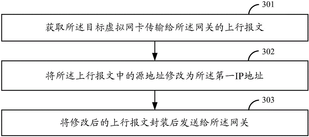
[0089] Such as Figure 3A What is shown is a flowchart of another embodiment of the virtual network card data transmission method of the present invention. Based on the foregoing embodiment, the method describes how to transmit a message through the target virtual network card configured with the second IP address A processing process of including the following steps:
[0090] In step 301, an uplink packet transmitted by the target virtual network card to the gateway is obtained. Wherein, the source address of the uplink packet is the second IP address.
[0091] The uplink message refers to a message sent to the VPN gateway device. Since the target virtual network card is configured as the second IP address by the client, the source address of the uplink message is the second IP address.
[0092] In step 302, the source address in the uplink message is modified to the first IP address.
[0093] Since the IP address of the target virtual network card recorded in the gateway is the first IP address, the source address of the uplink packet needs to be modified from the second IP address to the first IP address.
[0094] In an optional implementation manner, the modifying the source address of the uplink packet to the first IP address includes:
[0095] Search for the first IP address corresponding to the target virtual network card and the second IP address in the preset address record table; wherein, the target virtual network card, the first IP address and the second IP address are recorded in the address record table. Correspondence of IP addresses.
[0096] Replace the field value of the source address field in the uplink packet with the first IP address.
[0097] In this embodiment, the address record table can be set in advance, and the correspondence between the target virtual network card, the first IP address, and the second IP address in the address record table can be used to modify the source address of the message. Look up the address record table to obtain the first IP address corresponding to the target virtual network card and the second IP address.
[0098] It can be seen from the foregoing embodiment that when modifying the source address in the uplink message, the field value corresponding to the source address field in the message is replaced with the first IP address according to the message format, and the address modification process does not need to change the message. Text format, high processing efficiency, will not affect the transmission speed of the message.
[0099] In step 303, the modified uplink message is encapsulated and sent to the gateway.
[0100] After the modification, the source address recorded in the uplink message is the first IP address recorded in the gateway, so that the gateway can accurately obtain the information in the uplink message and ensure that the gateway can correctly forward the uplink message.
[0101] For example, such as Figure 3B Shown is a schematic diagram of an uplink message shown in an embodiment of the present invention. In the uplink message, the source address (SRC IP field) recorded in the message is the first IP address configured by the gateway: 3.3.3.3; because the client In order to prevent conflicts, the target virtual network card has been configured to 2.2.2.2, so the field value of the SRC IP field is replaced with 2.2.2.2, such as Figure 3C What is shown is a schematic diagram of a modified uplink packet according to an embodiment of the present invention.
[0102] As can be seen from the above embodiment, since the terminal configures the second IP address for the target virtual network card, and the target virtual network card recorded by the gateway is the first IP address, the terminal modifies the source address of the uplink packet to the first IP address when sending the uplink packet. IP address, so that the gateway can accurately obtain the information in the uplink packet, and ensure that the gateway can correctly forward the uplink packet.
[0103] Such as Figure 4A What is shown is a flowchart of another embodiment of the virtual network card data transmission method of the present invention. Based on the foregoing embodiment, the method describes how to transmit a message through the target virtual network card configured with the second IP address Another processing process includes the following steps:
[0104] In step 401, a downlink message sent by the gateway to the target virtual network card is received. Wherein, the destination address of the downlink message is the first IP address.
[0105] The downlink message refers to a message delivered by the VPN gateway device. Since the target virtual network card recorded in the gateway is the first IP address, the destination address of the uplink message is the first IP address. The client can distinguish the target network card that receives the message by the port number of the downlink message.
[0106] In step 402, the destination address in the downlink message is modified to the second IP address.
[0107] Since the IP address of the target virtual network card recorded in the client is the second IP address, the destination address in the downlink message needs to be modified from the first IP address to the second IP address.
[0108] In an optional implementation manner, the modifying the destination address of the downlink message to the second IP address includes:
[0109] Search for the second IP address corresponding to the target virtual network card and the first IP address in the preset address record table; wherein, the target virtual network card, the first IP address, and the second IP address are recorded in the address record table. Correspondence of IP addresses.
[0110] Replace the field value of the destination address field in the downlink message with the second IP address.
[0111] In this embodiment, the address record table can be set in advance, and the correspondence between the target virtual network card, the first IP address, and the second IP address in the address record table can be used to modify the destination address of the message. Look up the address record table to obtain the second IP address corresponding to the target virtual network card and the first IP address.
[0112] It can be seen from the above embodiment that when modifying the destination address in the uplink message, the field value corresponding to the destination address field is replaced with the second IP address according to the message format, and the address modification process does not need to change the message format. High efficiency, will not affect the transmission speed of the message.
[0113] In step 403, the modified downlink message is sent to the target virtual network card.
[0114] After the modification, the destination address recorded in the downlink message is the second IP address configured by the client for the target virtual network card, so the downlink message can smoothly reach the target virtual network card.
[0115] For example, such as Figure 4B Shown is a schematic diagram of a downlink message shown in an embodiment of the present invention. The destination address (DST IP field) recorded in the downlink message is the first IP address configured by the gateway: 2.2.2.2; because the client is preventing The conflict has configured the target virtual network card to 3.3.3.3, so replace the field value of the DSTIP field with 3.3.3.3, such as Figure 4C What is shown is a schematic diagram of a modified downlink message shown in an embodiment of the present invention.
[0116] It can be seen from the above embodiment that since the terminal configures the second IP address for the target virtual network card and the target virtual network card recorded by the gateway is the first IP address, the terminal modifies the destination address of the downlink message when receiving the downlink message from the gateway It is the second IP address, so that the downlink message can reach the target virtual network card smoothly.
[0117] Corresponding to the foregoing embodiment of the virtual network card data transmission method, the present invention also provides an embodiment of the virtual network card data transmission device.
[0118] The embodiment of the data transmission device of the virtual network card of the present invention can be implemented by software, or by hardware or a combination of software and hardware. Taking software implementation as an example, as a logical device, it is formed by reading the corresponding computer program instructions in the non-volatile memory into the memory through the processor of the device where it is located. From the hardware level, such as Figure 5 Shown is a hardware structure diagram of the device where the data transmission device of the virtual network card of the present invention is located, except Figure 5 In addition to the processor, memory, network interface, and non-volatile memory shown, the device in which the device is located in the embodiment may generally include other hardware, such as a forwarding chip responsible for processing messages. In terms of hardware structure, this The device may also be a distributed device, which may include multiple interface cards to expand the message processing at the hardware level. In the embodiment, the device where the device is located is usually based on the actual function of the data transmission device of the virtual network card, and may also include other hardware, which will not be repeated here.
[0119] Please refer to Image 6 , Is a block diagram of an embodiment of a data transmission device for a virtual network card of the present invention. The device includes: an address acquisition unit 610, a detection unit 620, a configuration unit 630, and a transmission unit 640.
[0120] Wherein, the address obtaining unit 610 is configured to obtain the first IP address allocated by the gateway to the target virtual network card.
[0121] The detecting unit 620 is configured to detect whether the first IP address and the IP address of the preset network card are in the same network segment.
[0122] The configuration unit 630 is configured to configure the target virtual network card with a first IP address that is not in the same network segment as the IP address of the preset network card when the first IP address and the IP address of the preset network card are in the same network segment. Two IP address.
[0123] The transmission unit 640 is configured to transmit packets through the target virtual network card configured with the second IP address.
[0124] It can be seen from the above-mentioned embodiment that when obtaining the first IP address assigned by the gateway to the target virtual network card, the client in the embodiment of the present invention detects whether the first IP address is in the same network segment as the IP address of the preset network card; When the first IP address and the IP address of the preset network card are in the same network segment, configure the target virtual network card with a second IP address that is not in the same network segment as the IP address of the preset network card; because the gateway is the target virtual When the first IP address of the network card is in the same network segment as the IP addresses of other network cards, the target virtual network card is configured with a second IP address that is not in the same network segment as all other network cards, so data is transmitted through the target virtual network card It can prevent IP address conflicts, ensure user information security, and improve the reliability of information transmission. The embodiment of the present invention does not change the process of configuring the IP address of the gateway, and its transformation cost is low.
[0125] In an optional implementation manner, the transmission unit 640 includes: an uplink packet acquisition subunit 641, a first modification subunit 642, and a first sending subunit 643.
[0126] Wherein, the uplink packet obtaining subunit 641 is configured to obtain the uplink packet transmitted by the target virtual network card to the gateway; wherein the source address of the uplink packet is the second IP address.
[0127] The first modification subunit 642 is configured to modify the source address in the uplink packet to the first IP address.
[0128] The first sending subunit 643 is configured to encapsulate the modified uplink message and send it to the gateway.
[0129] Wherein, the first modification subunit 642 may include: a first search module 6421 and a first replacement module 6422.
[0130] The first search module 6421 is configured to search for the first IP address corresponding to the target virtual network card and the second IP address in a preset address record table; wherein the target virtual network card is recorded in the address record table , The corresponding relationship between the first IP address and the second IP address.
[0131] The first replacement module 6422 is configured to replace the field value of the source address field in the uplink packet with the first IP address.
[0132] As can be seen from the above embodiment, since the second IP address is configured for the target virtual network card, and the target virtual network card recorded by the gateway is the first IP address, the source address of the uplink packet is modified to the first IP address when sending the uplink packet to the gateway. IP address, so that the gateway can accurately obtain the information in the uplink packet, and ensure that the gateway can correctly forward the uplink packet. Wherein, when the source address in the uplink message is modified, the field value corresponding to the source address field is replaced with the first IP address according to the message format. The address modification process does not need to change the message format, and the processing efficiency is high. Will not affect the transmission speed of the message.
[0133] In another optional implementation manner, the transmission unit 640 includes a downlink packet receiving subunit 644, a second modifying subunit 645, and a second sending subunit 646.
[0134] Wherein, the downlink message receiving subunit 644 is configured to receive the downlink message sent by the gateway to the target virtual network card; wherein, the destination address of the downlink message is the first IP address.
[0135] The second modification subunit 645 is configured to modify the destination address in the downlink message to the second IP address.
[0136] The second sending subunit 646 is configured to send the modified downlink message to the target virtual network card.
[0137] Wherein, the second modification subunit 645 may include: a second search module 6451 and a second replacement module 6452.
[0138] Wherein, the second search module 6451 is configured to search for a second IP address corresponding to the target virtual network card and the first IP address in a preset address record table; wherein, the address record table records the target The correspondence between the virtual network card, the first IP address, and the second IP address.
[0139] The second replacement module 6452 is configured to replace the field value of the destination address field in the downlink message with the second IP address.
[0140] As can be seen from the above embodiment, since the second IP address is configured for the target virtual network card, and the target virtual network card recorded by the gateway is the first IP address, the destination address of the downlink message is modified to the first IP address when the downlink message from the gateway is received. Two IP addresses, so that the downstream messages can reach the target virtual network card smoothly. Wherein, when modifying the destination address in the uplink message, the field value corresponding to the destination address field is replaced with the second IP address according to the message format. The address modification process does not need to change the message format, and the processing efficiency is high. Will not affect the transmission speed of the message.
[0141] As for the device embodiment, since it basically corresponds to the method embodiment, the relevant part can refer to the part of the description of the method embodiment. The device embodiments described above are merely illustrative. The units described as separate components may or may not be physically separated, and the components displayed as units may or may not be physical units, that is, they may be located in One place, or it can be distributed to multiple network units. Some or all of the modules can be selected according to actual needs to achieve the purpose of the solution of the present application. Those of ordinary skill in the art can understand and implement it without creative work.
[0142] The above descriptions are only the preferred embodiments of this application and are not intended to limit this application. Any modification, equivalent replacement, improvement, etc. made within the spirit and principle of this application shall be included in this application Within the scope of protection.

PUM

no PUM

Description & Claims & Application Information

We can also present the details of the Description, Claims and Application information to help users get a comprehensive understanding of the technical details of the patent, such as background art, summary of invention, brief description of drawings, description of embodiments, and other original content. On the other hand, users can also determine the specific scope of protection of the technology through the list of claims; as well as understand the changes in the life cycle of the technology with the presentation of the patent timeline. Login to view more.

Similar technology patents

Wireless remote communication method and wireless remote communication device

PendingCN109615840AGuaranteed to workEnsure information security
Owner:北方通用电子集团有限公司

Information coding structure based on circumference arrangement step array

ActiveCN106778990AEnsure information securityincrease flexibility
Owner:杭州泓林科技有限公司

Method and system for protecting safety of virtual machine under virtual platform network isolation

ActiveCN111258712AEnsure information security
Owner:SUZHOU LANGCHAO INTELLIGENT TECH CO LTD

Banking outlet customer behavior analysis method and device

PendingCN114707556AEnsure information security
Owner:BANK OF CHINA

Gateway protection method and device, computer equipment and storage medium

InactiveCN110995658AGuaranteed not to be tampered withEnsure information security
Owner:SWIFTPASS TECH CO LTD

Classification and recommendation of technical efficacy words

  • Ensure information security
  • Improve reliability

Screen recording method, screen recording device and terminal

InactiveCN107958168Aavoid being leakedEnsure information security
Owner:GUANGDONG OPPO MOBILE TELECOMM CORP LTD

Smart home equipment binding method and system, smart home equipment and mobile terminal

ActiveCN110572305AEnsure information securityimprove security
Owner:GREE ELECTRIC APPLIANCES INC OF ZHUHAI

Reading method and device for verification information

ActiveCN105207775APrevent stealing authentication informationEnsure information security
Owner:BEIJING QIHOO TECH CO LTD

Group signature-based supervisible block chain transaction privacy protection method and system

PendingCN113761582AEnsure information security
Owner:SHANDONG COMP SCI CENTNAT SUPERCOMP CENT IN JINAN

Small hydroelectric power mobile terminal monitoring method based on embedded industrial computer

InactiveCN105867342AEnsure information securityavoid misuse
Owner:ZHEJIANG UNIV OF TECH

Multiple branch predictions

ActiveUS20050268075A1improve reliabilityfacilitate availability
Owner:ORACLE INT CORP

Implantable lead

ActiveUS20100137928A1good flexibility , fatigue resistance and flex lifeimprove reliability
Owner:WL GORE & ASSOC INC
Why Eureka
Try Eureka