Exhaust system structure for internal combustion engine
A technology for exhaust systems and internal combustion engines, applied to internal combustion piston engines, exhaust devices, exhaust treatment, etc., to achieve the effect of reducing the deposition of urea
- Summary
- Abstract
- Description
- Claims
- Application Information
AI Technical Summary
Problems solved by technology
Method used
Image
Examples
Embodiment 1
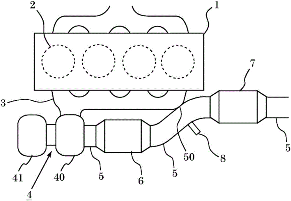
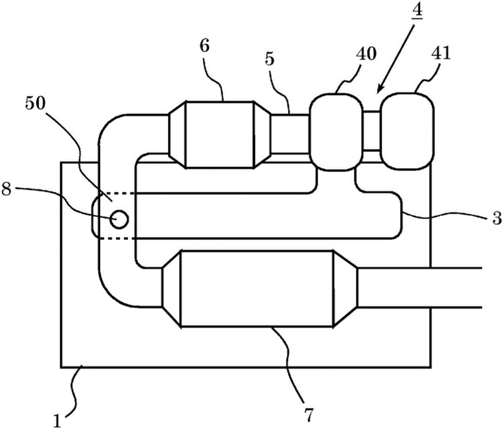
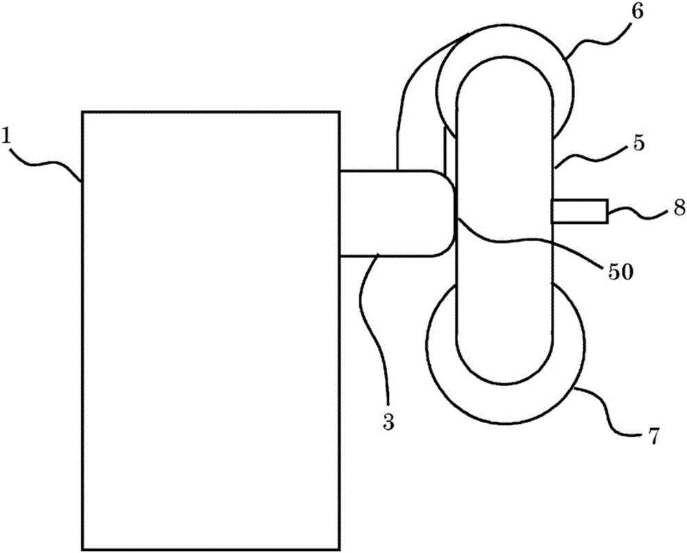
[0054] First, refer to Figure 1 to Figure 6 A first embodiment of the present invention will be described. figure 1 is a schematic diagram showing the structure of an exhaust system for an internal combustion engine according to the present invention.
[0055] figure 1 The internal combustion engine 1 shown is a compression ignition internal combustion engine 1 (diesel engine) with a plurality of cylinders. The internal combustion engine 1 may be a spark ignition internal combustion engine (gasoline engine) operating in a lean state.
[0056] The internal combustion engine 1 is connected to an exhaust manifold 3 . The exhaust manifold 3 includes a plurality of branch pipes through which burned gas (exhaust gas) is discharged from the cylinders 2 of the internal combustion engine 1 , and a merging portion where the branch pipes merge.
[0057] The junction of the exhaust manifold 3 is connected to the inlet of a turbine housing 40 which is part of the turbocharger 4 . The...
Embodiment 2
[0076] Below, will refer to Figure 7 to Figure 9 A second embodiment of the present invention will be described. Hereinafter, features different from those in the first embodiment will be described, and similar features will not be described.
[0077] In the first embodiment, the case has been described where the heat receiving portion is provided on the portion of the exhaust pipe 5 that the urea aqueous solution injected through the addition valve 8 impacts. In this embodiment, the case where the heat storage portion is provided on the impact portion will be described.
[0078] Figure 7 is a schematic diagram showing the structure of an exhaust system for an internal combustion engine in this embodiment. exist Figure 7 In , the same components as those in the first embodiment described above are marked by the same reference numerals. exist Figure 7 In the illustrated exhaust system configuration, the heat storage unit 52 is provided on a portion of the exhaust pipe 5...
PUM
 Abstract
Description
Claims
Application Information
 - R&D
- Intellectual Property
- Life Sciences
- Materials
- Tech Scout
- Unparalleled Data Quality
- Higher Quality Content
- 60% Fewer Hallucinations
Browse by: Latest US Patents, China's latest patents, Technical Efficacy Thesaurus, Application Domain, Technology Topic, Popular Technical Reports.
© 2025 PatSnap. All rights reserved.Legal|Privacy policy|Modern Slavery Act Transparency Statement|Sitemap|About US| Contact US: help@patsnap.com


