Reactor and method for preparing particle material

A granular material and granular material bed technology, applied in the field of granular material preparation, can solve problems such as difficult to meet continuous production, clogging, and easy bonding of particles

Active Publication Date: 2012-09-19
储晞
View PDF3 Cites 4 Cited by
  • Summary
  • Abstract
  • Description
  • Claims
  • Application Information

AI Technical Summary

Problems solved by technology

[0010] After the raw material gas is sent into the reactor cavity, it needs to pass through the set gas distributor, so that the raw material gas can react as fully as possible in the reaction chamber to improve the utilization rate of the raw material gas and the yield of the particle product. The cavity decomposes at any time, causing the air inlet and the air inlet of the gas distributor to be blocked due to particle deposition, which needs to be cleaned regularly, which not only reduces the product yield, but also makes it difficult to meet the needs of continuous production;
[0011] In addition to depositing on the surface of the particle seeds, the elemental substances decomposed by the raw material gas in the reactor cavity will also form deposits on the inner wall of the cavity, the inlet of the raw material gas and the pipeline, which reduces the product yield and affects the long-term continuous stability of the fluidized bed run;
[0012] The raw material gas decomposes to form simple substance deposition, which makes the particle seeds grow up, and also causes the particles to easily bond and form agglomeration in the cavity, which affects the collection of products, and can only interrupt production for necessary treatment;

Method used


Image

  • Reactor and method for preparing particle material
  • Reactor and method for preparing particle material
  • Reactor and method for preparing particle material

Examples


Embodiment 1

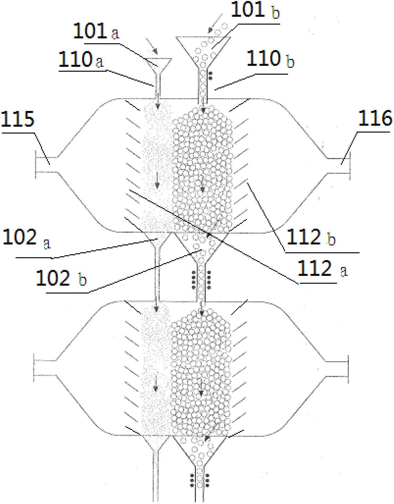
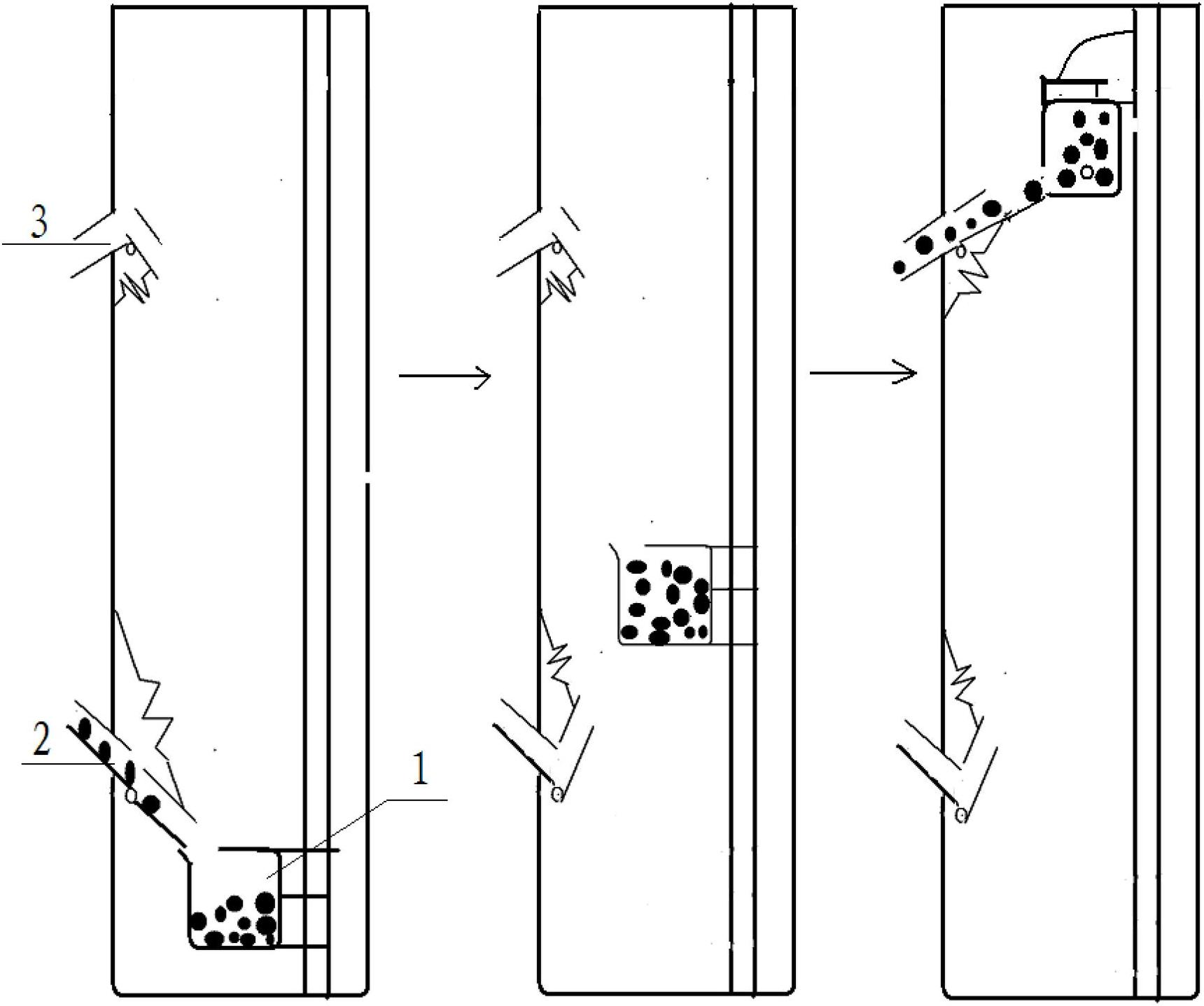
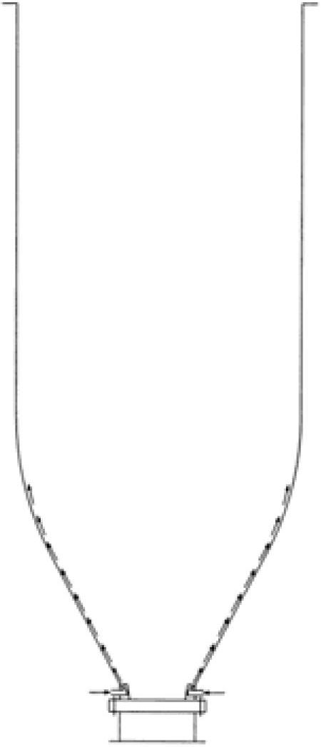
[0103] figure 1 Schematic diagram of the reactor structure for the preparation of granular materials provided in Example 1; figure 2 It is a schematic diagram of the structure of the particle conveying mechanism; Figure 3a , Figure 3b is a schematic diagram of the structure of the reactor cavity gas curtain; Figure 3c , Figure 3d It is a schematic diagram of the structure of the raw material gas pipeline air curtain;

[0104] like figure 1 As shown, the reactor for preparing granular materials provided in this embodiment includes: a two-stage reactor cavity, which constitutes a two-stage reaction, the height of the reactor cavity is 0.5 meters, and the height of the reactor is 1.5 meters.

[0105] The reactor cavity is used to form a packed particle bed, and the filling rate of the granular material seeds is more than 50%. The upper end of the first reactor cavity is respectively provided with a first feeding port 101a and a second feeding port 101b, and the lower e...

Embodiment 2

[0140] Figure 4 Schematic diagram of the reactor structure for the preparation of granular materials provided in Example 2.


PUM

PropertyMeasurementUnit
heightaaaaaaaaaa
heightaaaaaaaaaa
heightaaaaaaaaaa

Abstract

The invention discloses a reactor and method for preparing a particle material. The reactor for preparing the particle material comprises more than one reactor cavity body, wherein each reactor cavity body is used for forming and stacking a particle bed layer; the upper end of each reactor cavity body is respectively provided with a first feeding port and a second feeding port; the lower end thereof is correspondingly provided with a first discharging port and a second discharging port; a raw material gas inlet is arranged on the sidewall of the reactor cavity body at one side close to the first feeding port and the first discharging port; a tail gas outlet is arranged on the sidewall of the reactor cavity body at to one side close to the second feeding port and the second discharging port; a first distributor and a second distributor are respectively arranged inside the reactor cavity body to be close to the raw material gas inlet and the tail gas outlet; and each reactor cavity body is externally or internally provided with a dynamic generating mechanism. The invention also discloses a method for preparing the particle material. According to the reactor and method for preparing the particle material, disclosed by the invention, a plurality of disadvantages in the prior art are overcome, and efficient and energy-saving, long-term and steady, safe and reliable preparation of the particle material is realized.

Description

technical field [0001] The invention relates to the preparation technology of granular materials, in particular to a reactor and a method for preparing granular materials. Background technique [0002] In the modern industrial production process, the demand for granular materials such as silicon, nickel and titanium, and compounds such as silicon nitride, silicon carbide and silicon oxide is increasing, and the requirements for their performance are becoming more and more stringent: Granular materials must meet high purity requirements; and the particle size is uniform and moderate; the production cost of granular materials should not be too high to meet the needs of large-scale continuous production. [0003] At present, the preferred reactor for the production of granular materials is a fluidized bed reactor, using selected raw material gases (gases that can be decomposed at high temperatures, or undergo reduction, oxidation, nitriding, etc., and contain target material el...

Claims


Application Information

Patent Timeline
Patent Type & Authority Applications(China)
IPC IPC(8): B01J12/02C01B33/021C01B32/05
Inventor 储晞
Owner 储晞
Why Eureka
Try Eureka