Supercharge Your Innovation With Domain-Expert AI Agents!

Rotary automatic mechanical arm

A technology of manipulator and manipulator, applied in the field of automation, can solve the problems of high manufacturing cost, rising cost, complex structure, etc., and achieve the effect of improving product yield, improving work efficiency and ensuring continuity

Inactive Publication Date: 2016-09-21
易拓威(上海)机器人科技有限公司
View PDF0 Cites 13 Cited by
  • Summary
  • Abstract
  • Description
  • Claims
  • Application Information

AI Technical Summary

Problems solved by technology

Existing rotary grippers are generally used for heavy-duty or complex-shaped workpieces such as cylinders. However, these grippers are adjusted by multiple sensors, the structure is relatively complicated, and the manufacturing cost is high, resulting in an increase in the final cost.

Method used


Image

  • Rotary automatic mechanical arm
  • Rotary automatic mechanical arm
  • Rotary automatic mechanical arm

Examples


Embodiment

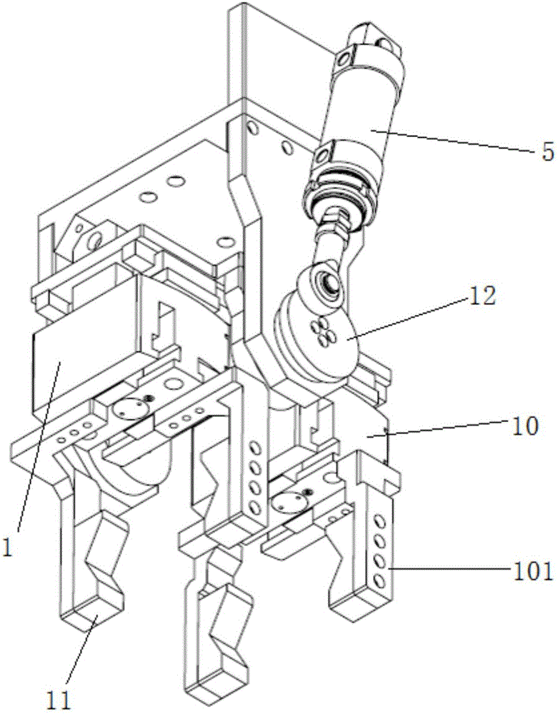
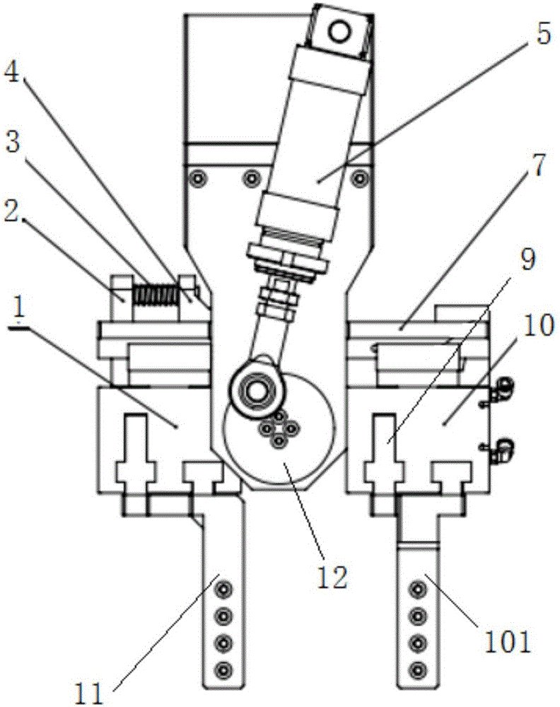
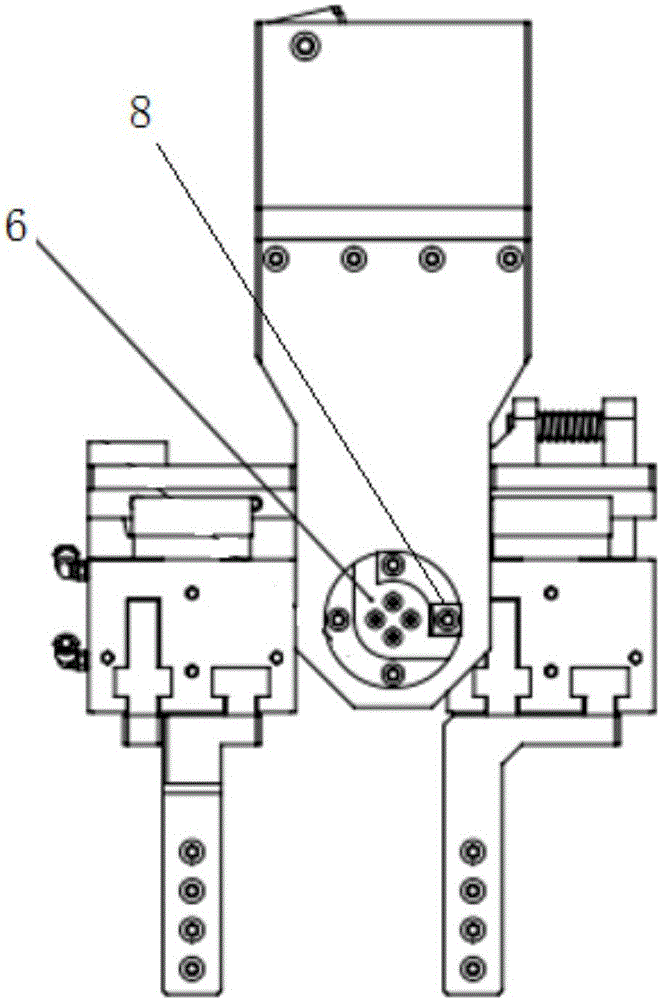
[0023] A rotatable automatic manipulator, its structure is as follows figure 1 , figure 2 and image 3 As shown, the manipulator includes a cylinder 5, a mounting plate 7, an L-shaped bumper 6, a fixed air gripper 10 and a follower air gripper 1, the upper end of the fixed air gripper 10 is connected to one side of the installation plate 7, and the upper end of the follower air gripper 1 Slidingly connected to the other side of the mounting plate 7, the inner side of the fixed claw runs through a rotating shaft and can rotate synchronously with the rotating shaft, one end of the rotating shaft is connected to the cylinder 5 through the turntable 12, and the center of the rotating shaft is fixedly connected to the turntable 12 , the cylinder 5 is fixedly connected to the outside of the turntable; the other end of the rotating shaft is provided with a positioning block 8 that matches the collision block 6, and the positioning block 8 can move in an arc between the two sides of...


PUM


Abstract

The invention relates to a rotary automatic mechanical arm. The mechanical arm comprises an air cylinder, a positioning device, a fixed pneumatic claw and a following pneumatic claw. The upper end of the fixed pneumatic claw and the upper end of the following pneumatic claw are connected to the two sides of an installing plate. A rotating shaft penetrates the inner side of the fixed pneumatic claw, and the fixed pneumatic claw can synchronously rotate with the rotating shaft. One end of the rotating shaft is connected with the air cylinder through a rotary disc, and a positioning block matched with the positioning device is arranged at the other end of the rotating shaft. When the air cylinder lifts or contracts, the rotary disc rotates, the rotating shaft is driven to rotate, the rotating shaft rotates within a certain range through the positioning device, the fixed pneumatic claw is driven to rotate through rotation of the rotating shaft, and the following pneumatic claw is driven by the installing plate to rotate. Compared with the prior art, the rotary automatic mechanical arm is high in flexibility and suitable for various components of different specifications, it is guaranteed that a workpiece is closely attached to a positioning chuck of a machine tool through the following pneumatic claw, feeding is stable and reliable, and a good foundation is laid for finish machining of the machine tool.

Description

technical field [0001] The invention relates to the field of automation, in particular to a rotatable automatic manipulator. Background technique [0002] At present, with the gradual increase of labor costs, industrial automation applications are becoming more and more popular. In the machine tool processing line system, the attitude change of the workpiece is the basis for realizing the assembly line processing operation and improving the processing and manufacturing efficiency. In some of today's automated loading and unloading systems, a shelving table is generally placed between the machine tools, or a turning mechanism is installed to achieve various posture changes of the workpiece, which increases the movement of the manipulator and increases the work of manipulator loading and unloading. the beat. Existing rotary grippers are generally used for heavy-duty or complex-shaped workpieces such as cylinder blocks. However, these grippers are adjusted by multiple sensors...

Claims


Application Information

Patent Timeline
IPC IPC(8): B25J9/14B25J9/16B25J15/02
CPCB25J9/1679B25J9/146B25J9/1612B25J15/0253
Inventor 李延平陈剑波时豹王智
Owner 易拓威(上海)机器人科技有限公司
Features
  • R&D
  • Intellectual Property
  • Life Sciences
  • Materials
  • Tech Scout
  • Unparalleled Data Quality
  • Higher Quality Content
  • 60% Fewer Hallucinations
Learn More