
Axle Meter Axle Sensing Device

A technology of sensing device and wheel sensor, which is applied in transportation and packaging, railway car body parts, vehicle route interaction equipment, etc., can solve problems such as jitter interference, poor contact signal, and inability to perform effective protection, so as to eliminate interference Signal, improve the effect of anti-interference ability

Active Publication Date: 2017-11-03
邳州市鑫盛创业投资有限公司
View PDF6 Cites 0 Cited by
  • Summary
  • Abstract
  • Description
  • Claims
  • Application Information

AI Technical Summary

Problems solved by technology

[0002] The track surface of the track circuit is affected by bad conductors, causing poor track circuit shunting. When a train or locomotive occupies the track, the track relay that controls the track section cannot operate normally, resulting in signal interlock failure.
When the axle counting sensor solution is adopted, the mechanical sensor relies on the spring to control the on-off of the electrode contacts to generate the signal of the arrival of the train, which is prone to poor contact and signal jitter interference; the infrared rays of the infrared sensor are easily blocked by dust and debris, and are easily affected. The interference of other light produces interference pulses; the ultrasonic piezoelectric transducer cannot be effectively protected because it must be exposed, and is also susceptible to interference from other obstacles such as construction workers, resulting in interference pulses; eddy current coil induction, magnetic head sensor induction It is easily affected by metal debris. For example, when a railway construction worker slides a shovel over the magnetic head sensor, it is easy to cause interference to the magnetic head discrimination and output interference pulses
When the above-mentioned various sensors enter or exit the detection interval, due to the vibration of the sensor caused by the passing of the vehicle, the vibration of the wheel itself, and the vibration of the sensor's own contacts, etc., it will also cause the edge of the sensor signal to generate a jitter pulse.

Method used


Image

  • Axle Meter Axle Sensing Device
  • Axle Meter Axle Sensing Device
  • Axle Meter Axle Sensing Device

Examples


Embodiment Construction

[0021] The present invention will be further described below in conjunction with accompanying drawing.

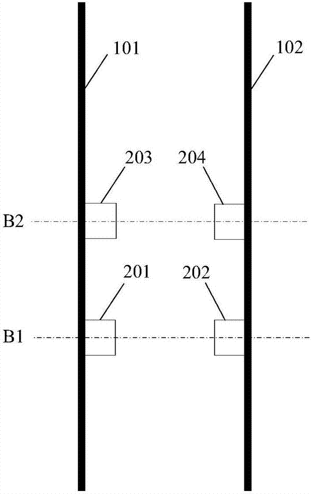
[0022] Such as figure 1 Shown is an embodiment of the installation position of the wheel sensor in the axle sensor device of the axle meter. The first left wheel sensor 201 and the first right wheel sensor 202 are installed on the inner sides of the left track 101 and the right track 102 respectively, and are on the same vehicle axis B1. When the locomotive or train is running, when the wheel axle moves to the position of the vehicle axis B1, the left wheel sensor 201 and the right wheel sensor 202 respectively sense the left and right wheels and output valid signals at the same time. The left wheel sensor 201 and the right wheel sensor 202 need to be installed on the outside or inside of the left and right rails respectively. They can be installed on the outside or the inside of the rail at the same time or respectively, but must be on the same vehicle axis, that is, the ...


PUM


Abstract

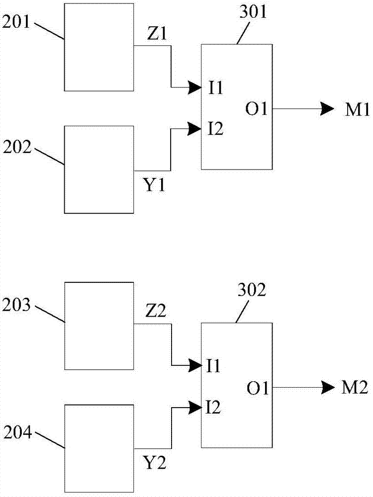
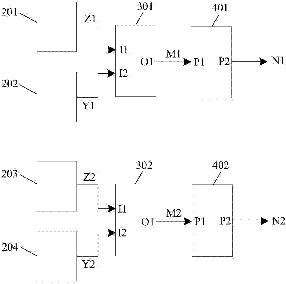
Provided is an axle counting sensing device for outputting 2 axle counting signals. Each axle counting signal is used for detecting wheels through two wheel sensors mounted on a left track and a right track, and the output axle counting signals are effective only when the two wheel sensors mounted on the left track and the right track detect the wheels and output the effective signals at the same time. Narrow impulse interference and signal edge shaking interference in the axle counting signals are filtered out by a pulse interference eliminating unit, the anti-interference capacity is further improved, and the maximum width of positive narrow pulses and negative narrow pulses capable of being filtered can be adjusted by changing the charging time constant and the discharge time constant. The device can be applied to the occasions on which locomotives and trains on tracks are subjected to wheel detection and axle counting.

Description

technical field [0001] The invention relates to the technical field of axle counting equipment, in particular to an axle counting sensor device. Background technique [0002] The track surface of the track circuit is badly shunted due to the influence of bad conductors. When a train or locomotive occupies the track, the track relay that controls the track section cannot operate normally, resulting in signal interlock failure. When the axle counting sensor solution is adopted, the mechanical sensor relies on the spring to control the on-off of the electrode contacts to generate the signal of the arrival of the train, which is prone to poor contact and signal jitter interference; the infrared rays of the infrared sensor are easily blocked by dust and debris, and are easily affected. The interference of other light produces interference pulses; the ultrasonic piezoelectric transducer cannot be effectively protected because it must be exposed, and is also susceptible to interfer...

Claims


Application Information

Patent Timeline
Patent Type & Authority Patents(China)
IPC IPC(8): B61L1/16
CPCB61L1/165B61L1/167
Inventor 凌云陈刚文定都郭艳杰
Owner 邳州市鑫盛创业投资有限公司
Learn More