Eureka AIR delivers breakthrough ideas for toughest innovation challenges, trusted by R&D personnel around the world.

An automatic jet-flow floating breakwater and its wave-absorbing method

A floating breakwater, automatic technology, applied in the direction of breakwaters, embankments, jetties, etc., can solve the problem of wasting money, save energy, enhance wave absorption performance, and meet the requirements of safe operation.

Active Publication Date: 2019-02-15
OCEAN UNIV OF CHINA
View PDF9 Cites 0 Cited by
  • Summary
  • Abstract
  • Description
  • Claims
  • Application Information

AI Technical Summary

Problems solved by technology

The existing solution is to spend more money to improve the overall wave absorption performance, resulting in a large waste of money to ensure the safety of the design under low probability events

Method used


Image

  • An automatic jet-flow floating breakwater and its wave-absorbing method

Examples


Embodiment 1

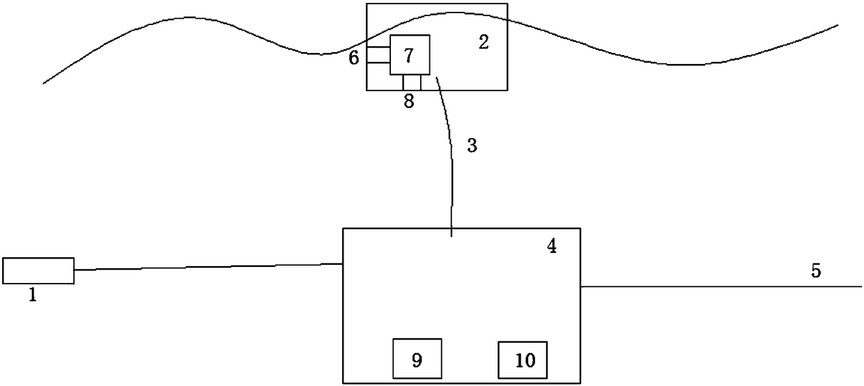
[0023] Example 1, such as figure 1 As shown, this embodiment discloses a new type of automatic jet floating breakwater, which includes a base 4 that sinks into the bottom of the water and a floating body 2 floating on the water surface. The base and the floating body are connected by anchor chains 3. Water pump 7, the water inlet 8 of this water pump is arranged on the lower part of the floating body, and the water outlet 6 is arranged on the facing wave side of the floating body; a single-chip microcomputer 9 is installed in the base, and a pressure wave height meter 1 is arranged in front of the facing wave side of the base. The wave height meter is electrically connected with the water pump, and the switch and flow of the water pump are controlled according to the data from the pressure type wave height meter. The single-chip microcomputer is electrically connected with the water pump switch 10 installed in the base, and controls the switch and flow of the water pump throug...

Embodiment 2

[0029] Embodiment 2. This embodiment discloses another new type of automatic jet floating breakwater, which includes a base that sinks into the bottom of the water and a floating body that floats on the water surface. The base and the floating body are connected by anchor chains, and a water pump is arranged in the floating body. , the water inlet of the water pump is set on the lower part of the buoyant body, and the water outlet is set on the facing wave side of the buoyant body; the bottom of the buoyant body is also provided with a waterproof box, and a single-chip microcomputer is installed in the waterproof box, and the probe of the pressure wave height meter is set on the outside of the waterproof box. On the wave side, the single-chip microcomputer is electrically connected with the pressure wave height meter and the water pump, and controls the switch and flow of the water pump according to the data from the pressure wave height meter. The single chip microcomputer is ...


PUM


Abstract

The invention discloses a novel automatic jet floating type breakwater. The breakwater comprises a base which sinks underwater and a floating body which floats on the water; the base is connected with the floating body by an anchor chain; a water pump is disposed in the floating body; the water inlet of the water pump is arranged on the lower part of the floating body, and the water outlet is arranged on the head sea side of the floating body; a single-chip microcomputer is mounted in the base; a pressure type wave height gauge is disposed on the front of the head sea side of the base; and the single-chip microcomputer is electrically connected with the pressure type wave height gauge and the water pump, and controls the switch on / off and volume of the water pump based on the data from the pressure type wave height gauge. The invention also discloses a wave eliminating method using the novel automatic jet floating type breakwater mentioned above, wherein, the wave elimination is performed by the floating body itself according to the designed wave condition of the breakwater. The novel automatic jet floating type breakwater disclosed by the invention can normally eliminate waves by the floating type breakwater itself, and can jet horizontal flow on the head sea side to enhance wave elimination performance when the single-chip microcomputer detects an extreme wave condition by the pressure type wave height gauge, therefore saves cost and meets the practical needs well at the same time.

Description

technical field [0001] The invention relates to the field of breakwaters, in particular to an automatic jet-flow floating breakwater and a wave elimination method in the field. Background technique [0002] Floating breakwater is a breakwater composed of wave-dissipating floating body and mooring equipment. The wave-dissipating floating body is composed of a box or floating row with a certain draft. On the water surface, the principle of wave dissipation is to use floating bodies to prevent wave propagation or break waves, and float up and down and swing back and forth under the action of waves to interfere with the movement of water particles in waves and destroy the water flow structure inside waves to achieve the purpose of reducing wave energy . It has the advantages of simple construction and construction, easy demolition, wave-dissipating floating body can adapt to large changes in water level, construction cost is less affected by water depth, etc., and can be used f...

Claims


Application Information

Patent Timeline
Patent Type & Authority Patents(China)
IPC IPC(8): E02B3/06
CPCE02B3/062Y02A10/11
Inventor 尹则高高成岩史宏达杨博李元马琳张欢冯颖楠贾茜茜邹威
Owner OCEAN UNIV OF CHINA
Why Eureka
Eureka Blog
Learn More