
A high-strength support plate

A support plate, high-strength technology, used in rocket launchers, offensive equipment, weapon types, etc., can solve problems such as easy to get stuck, low strength, strong pressure, etc.

Active Publication Date: 2018-02-02
BEIJING INST OF SPACE LAUNCH TECH +1
View PDF9 Cites 0 Cited by
  • Summary
  • Abstract
  • Description
  • Claims
  • Application Information

AI Technical Summary

Problems solved by technology

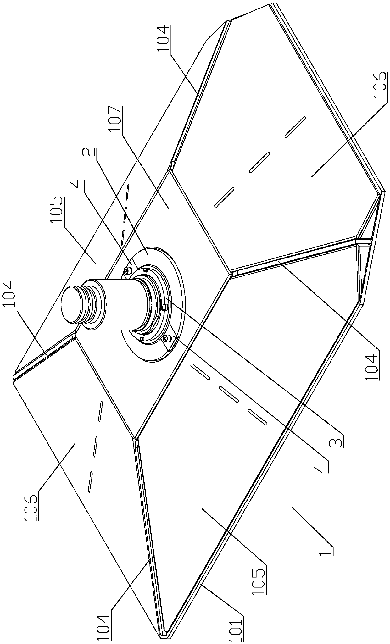
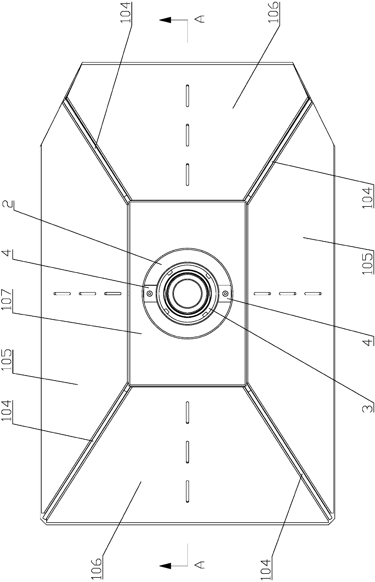
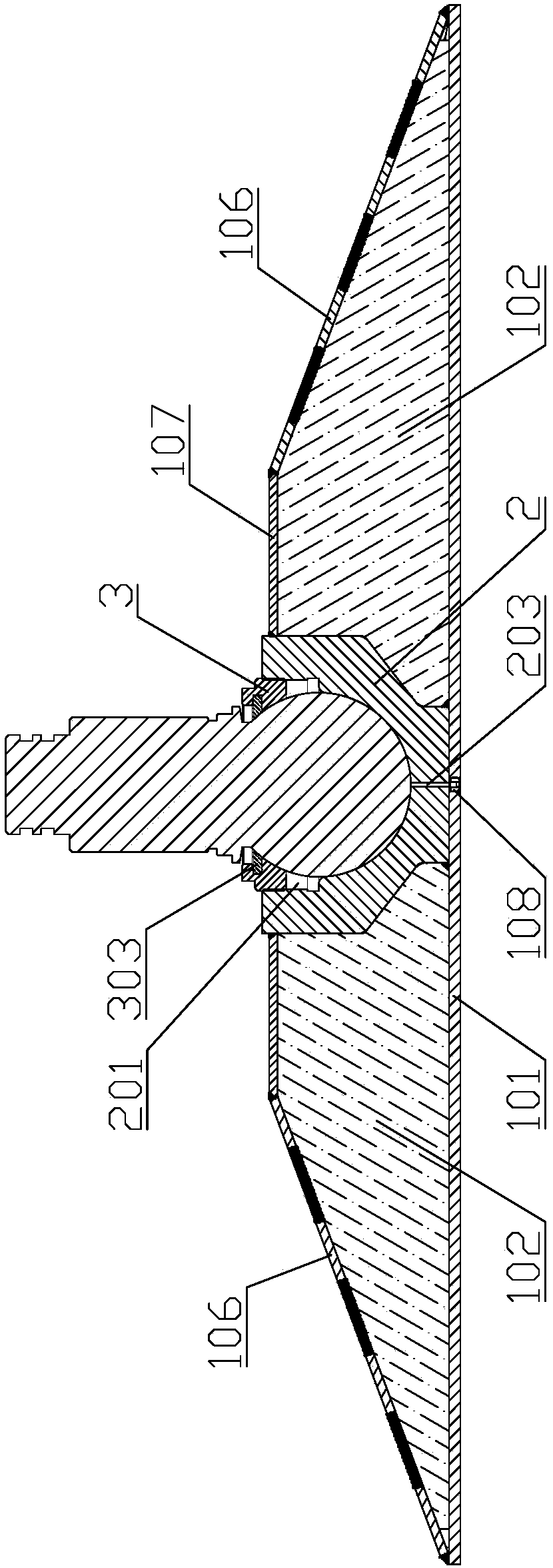
[0004] In order to solve the problems of low strength, small support force, strong pressure on the ground, easy deformation and sticking phenomenon of the conventional support plate in the prior art, the present invention provides a high-strength support plate, including a support seat and a support shaft, wherein: the support seat includes a base plate, two transverse rib plates, two longitudinal rib plates, four diagonal rib plates, two large cover plates, two small cover plates and an upper cover plate , the support shaft is vertically fixed on the middle part of the upper side of the bottom plate, and the two transverse stiffener plates are perpendicular to the upper side of the bottom plate and symmetrically distributed on both sides of the support shaft along the transverse direction. Welding and fixing; two longitudinal stiffeners are perpendicular to the upper side of the bottom plate and symmetrically distributed on both sides of the support shaft along the longitudinal direction, and the two longitudinal stiffeners are welded and fixed to the bottom plate and the support shaft; four diagonal stiffeners are vertical On the upper side of the bottom plate and distributed around the support shaft along the diagonal of the bottom plate, the four diagonal ribs are welded and fixed to the bottom plate and the support shaft; the upper cover plate is sleeved on the support shaft through the circular hole opened in the center and fixed by welding, and the upper cover plate covers the upper end faces of the transverse stiffener plate, longitudinal stiffener plate and diagonal stiffener plate; the two large cover plates cover the oblique end faces of the two longitudinal stiffener plates correspondingly and fixed by welding with the longitudinal rib plate through the opened welding hole, and the two large cover plates are welded and fixed with the bottom plate, the upper cover plate and the adjacent diagonal rib plate; the two small cover plates are correspondingly covered on the two The oblique end face of a transverse rib plate is welded and fixed with the transverse rib plate through the opened welding hole, and the two small cover plates are welded and fixed with the bottom plate, the upper cover plate and the adjacent diagonal rib plate; The upper end surface of the shaft is provided with a circular groove along the central axis, and the bottom of the circular groove is further provided with a spherical groove

Method used


Image

  • A high-strength support plate
  • A high-strength support plate
  • A high-strength support plate

Examples


Embodiment Construction

[0027] like Figure 1 to Figure 14Shown is a specific embodiment of a high-strength support disc of the present invention, which generally includes a support seat 1 and a support shaft 2 . Wherein, the support seat 1 specifically includes a bottom plate 101, two transverse rib plates 102, two longitudinal rib plates 103, four diagonal rib plates 104, two large cover plates 105, two small cover plates 106 and an upper cover plate 107 . Let the support shaft 2 be vertically fixed on the middle part of the upper side of the bottom plate 101, and the fixing method can be realized by welding. The two transverse stiffeners 102 are perpendicular to the upper side of the bottom plate 101 and symmetrically distributed on both sides of the support shaft 2 along the transverse direction, and the two transverse stiffeners 102 are welded to the bottom plate 101 and the support shaft 2 . Let the two longitudinal stiffeners 103 be perpendicular to the upper side of the bottom plate 101 and...


PUM


Abstract

The invention discloses a high-strength support disc, which comprises a support seat and a support shaft, wherein the support seat comprises a bottom plate, two transverse reinforcing rib plates, two longitudinal reinforcing rib plates, four diagonal reinforcing rib plates, two large cover plates, two small cover plates and an upper cover plate, wherein the support shaft is vertically fixed at the middle part of the upper side surface of the bottom plate; the two transverse reinforcing rib plates, the two longitudinal reinforcing rib plates and the four diagonal reinforcing rib plates are distributed on the periphery of the support shaft in the transverse and longitudinal directions and along the diagonal line, and are welded and fixed with the bottom plate and the support shaft; the upper cover plate sleeves the outer side of the support shaft through a round hole formed in the center and is welded and fixed; the two large cover plates and the two small cover plates are welded and fixed with the bottom plate, the upper cover plate and the adjacent diagonal reinforcing rib plates; the upper end surface of the support shaft is provided with a round groove along the axle line; and the groove bottom of the round groove is further provided with a spherical groove. The high-strength support disc has the advantages that the deformation cannot easily occur; the strength is high; the stress is strong; and the born stress can be uniformly distributed on the ground, so that the support force is improved.

Description

technical field [0001] The invention relates to a support device, in particular to a support plate with high strength and dustproof function. Background technique [0002] The support plate is a commonly used part of equipment such as cranes and support platforms, and its performance directly determines the stability and use effect of the support. Especially for special fields such as launch platforms of launch vehicles, the support plate is required to have the characteristics of large support force and low pressure to meet the requirements of special use conditions, which puts forward higher requirements for the strength and self-weight of the support plate. For example, for some types of launch vehicles, the launch platform is designed with 4 outriggers, and each leg is connected to a support plate to be supported from the ground. Not only the support force of the support plate is required to be as large as 60t, but also The pressure of the disk to the ground should be e...

Claims


Application Information

Patent Timeline
Patent Type & Authority Patents(China)
IPC IPC(8): F41F3/04
CPCF41F3/04
Inventor 蒋爱民赵黎明谢文建吴建胜徐轶群冯世泽
Owner BEIJING INST OF SPACE LAUNCH TECH
Learn More