A Method for Generating Curved Surface Machining Trajectories Based on Milling Force Prediction

A technology of trajectory generation and surface processing, which is applied in the field of metal cutting to achieve the effect of improving surface processing efficiency, improving surface quality and good surface smoothness

Inactive Publication Date: 2018-05-22
HARBIN UNIV OF SCI & TECH
View PDF7 Cites 0 Cited by
  • Summary
  • Abstract
  • Description
  • Claims
  • Application Information

AI Technical Summary

Problems solved by technology

The free-form surface can meet the exquisite appearance and performance requirements of modern products, but due to its high precision requirements, the free-form surface has become a hot and difficult research point in the field of CNC machining

Method used


Image

  • A Method for Generating Curved Surface Machining Trajectories Based on Milling Force Prediction
  • A Method for Generating Curved Surface Machining Trajectories Based on Milling Force Prediction
  • A Method for Generating Curved Surface Machining Trajectories Based on Milling Force Prediction

Examples


specific Embodiment approach 1

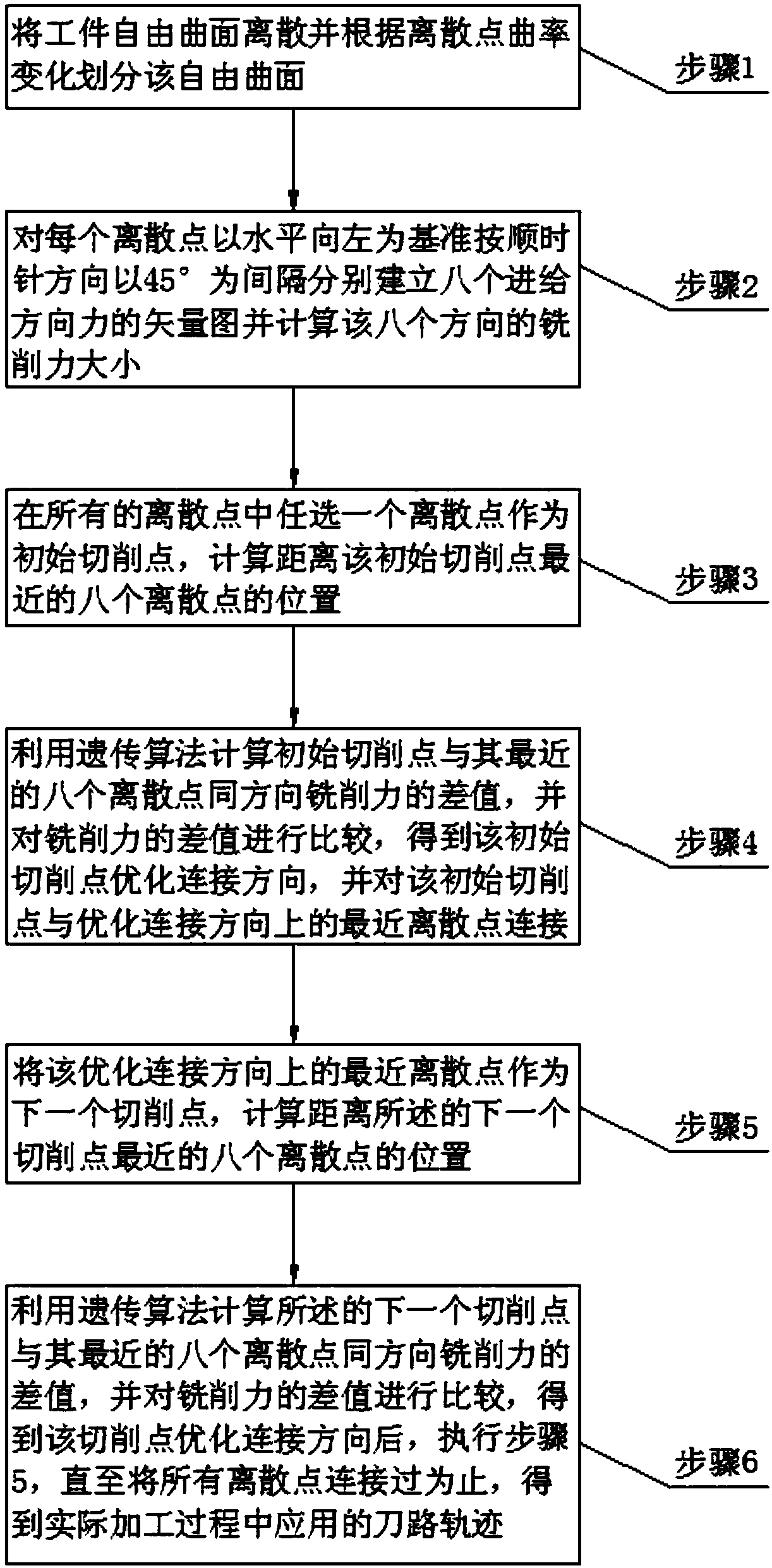
[0024] Specific implementation mode one: as figure 1 As shown, this embodiment discloses a method for generating curved surface machining trajectory based on milling force prediction, and the method includes the following steps:

[0025] Step 1: Discretize the free-form surface of the workpiece, and divide the free-form surface according to the curvature change of each discrete point;

[0026] Step 2: For each discrete point, take the horizontal left as the reference and clockwise at an interval of 45° to establish the vector diagrams of the eight feed direction forces and calculate the milling force in the eight directions;

[0027] Step 3: choose a discrete point among all the discrete points as the initial cutting point, and calculate the positions of the eight nearest discrete points from the initial cutting point;

[0028] Step 4: use genetic algorithm to calculate the milling force difference between the initial cutting point and its eight nearest discrete points in the...

specific Embodiment approach 2

[0031] Embodiment 2: A method for generating curved surface machining trajectory based on milling force prediction described in Embodiment 1. In step 1, the free-form surface of the workpiece is discretized, and the free-form surface is divided according to the curvature change of each discrete point. The specific method steps are:

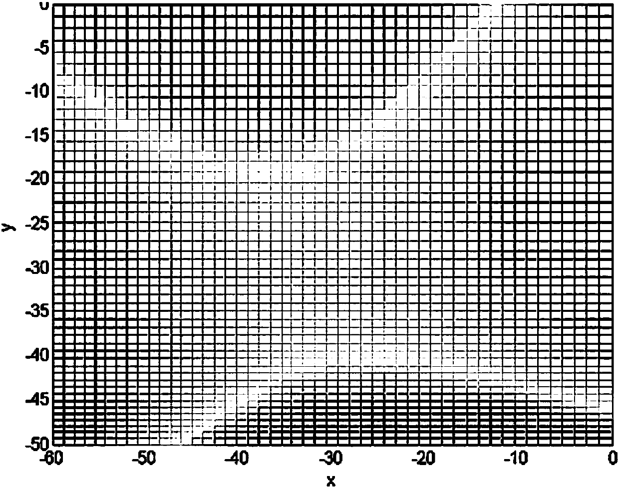
[0032] Step 1-1: The free-form surface of the workpiece is regarded as a patchwork of multiple simple surfaces, and the form of each simple surface is described as P(u, v), where P(u, v) is the parametric equation of the surface, u and v are two parameters satisfying 0≤u, v≤1;

[0033] In this embodiment, the selected surface parameter equation is as follows:

[0034]

[0035] The discrete results of the MATLAB two-dimensional simulation of the selected surface instance are as follows: figure 2 shown;

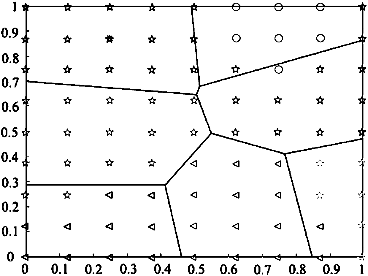
[0036] Step 1-2: According to the curvature of each discrete point, the free-form surface of the workpiece is divided into convex surface, ...

specific Embodiment approach 3

[0038] Specific embodiment three: a kind of method for generating curved surface machining trajectory based on milling force prediction described in specific embodiment one, in step 2, for each discrete point, take the horizontal direction to the left as the reference and clockwise with 45° as the interval respectively The specific method steps for establishing the vector diagrams of the eight feed direction forces and calculating the milling forces in the eight directions are:

[0039] Step 2-1: Approximately treat each simple surface as an inclined plane micro-element processing in any feed direction, and establish discrete points on this simple surface at intervals of 45° in a clockwise direction based on the horizontal to the left. The vector diagram of the force in the feed direction, such as Figure 4 shown;

[0040] Step 2-2: Since the microelement milling force calculation formula is established on the horizontal plane, and the conversion between the inclined plane an...


PUM


Abstract

A milling force prediction-based curved surface processing trajectory generation method relates to the metal milling processing field, and can limit the fluctuation of a milling force during a processing process, and improve the surface quality of a workpiece and the processing efficiency. The method comprises the steps of discretizing and dividing a workpiece curve; establishing a vector diagram of the forces of the discrete points, and calculating the milling force; selecting a discrete point at random as an initial point, calculating the positions of the nearest eight discrete points of the initial point; calculating the differences of the milling forces of the initial point and the nearest discrete points in the same direction, and comparing the differences to obtain an optimization connection direction of an initial cutting point; taking the nearest discrete point in the optimization connection direction as the next cutting point, and calculating the positions of the nearest eight discrete points of the next cutting point; obtaining an optimization connection direction of the cutting points by using the above method, repeating the last step until all discrete points are connected, thereby obtaining a tool path trajectory in the actual processing. The milling force prediction-based curved surface processing trajectory generation method of the present invention is used for the free curved surface cutting processing.

Description

technical field [0001] The invention relates to the field of metal cutting, in particular to a method for generating curved surface machining tracks based on milling force prediction. Background technique [0002] In the fields of aviation, shipbuilding, and automobile manufacturing, some curved surfaces with special transition curves, such as turbine blades, ship propellers, and automobile shapes, are often involved. Such curved surfaces are called free-form surfaces. Freeform surfaces can meet the exquisite appearance and performance requirements of modern products. However, due to their high precision requirements, freeform surfaces have become a hot and difficult research point in the field of CNC machining. Free-form surface NC programming is an important part of its digital design and manufacturing integration technology, and free-form surface machining tool path trajectory planning technology, as the core technology of free-form surface NC programming, has a pivotal p...

Claims


Application Information

Patent Timeline
Patent Type & Authority Patents(China)
IPC IPC(8): G05B19/19
CPCG05B19/19
Inventor 吴明阳陈勇程耀楠张芮赵旭
Owner HARBIN UNIV OF SCI & TECH
Why Eureka
Try Eureka