Liquid crystal display device

A technology of liquid crystal display device and liquid crystal layer, applied in liquid crystal materials, instruments, optics, etc., can solve the problems of increased ion density, reduced voltage holding ratio, white spot, etc., and achieves the effect of preventing white spot and preventing reduction.

Active Publication Date: 2016-09-21
DIC CORP
View PDF29 Cites 5 Cited by
  • Summary
  • Abstract
  • Description
  • Claims
  • Application Information

AI Technical Summary

Problems solved by technology

[0014] The present invention provides a liquid crystal display device using a liquid crystal composition containing a liquid crystal compound having a specific structure and a polymerizable liquid crystal composition containing a polymerizable liquid crystal compound having a specific structure at a specific ratio. Layer, so as to prevent the decrease of the voltage holding ratio (VHR) of the liquid crystal layer and the increase of the ion density (ID), and solve the problems of poor display such as white spots, uneven orientation, and burn-in

Method used


Image

  • Liquid crystal display device
  • Liquid crystal display device
  • Liquid crystal display device

Examples


Embodiment 1~4

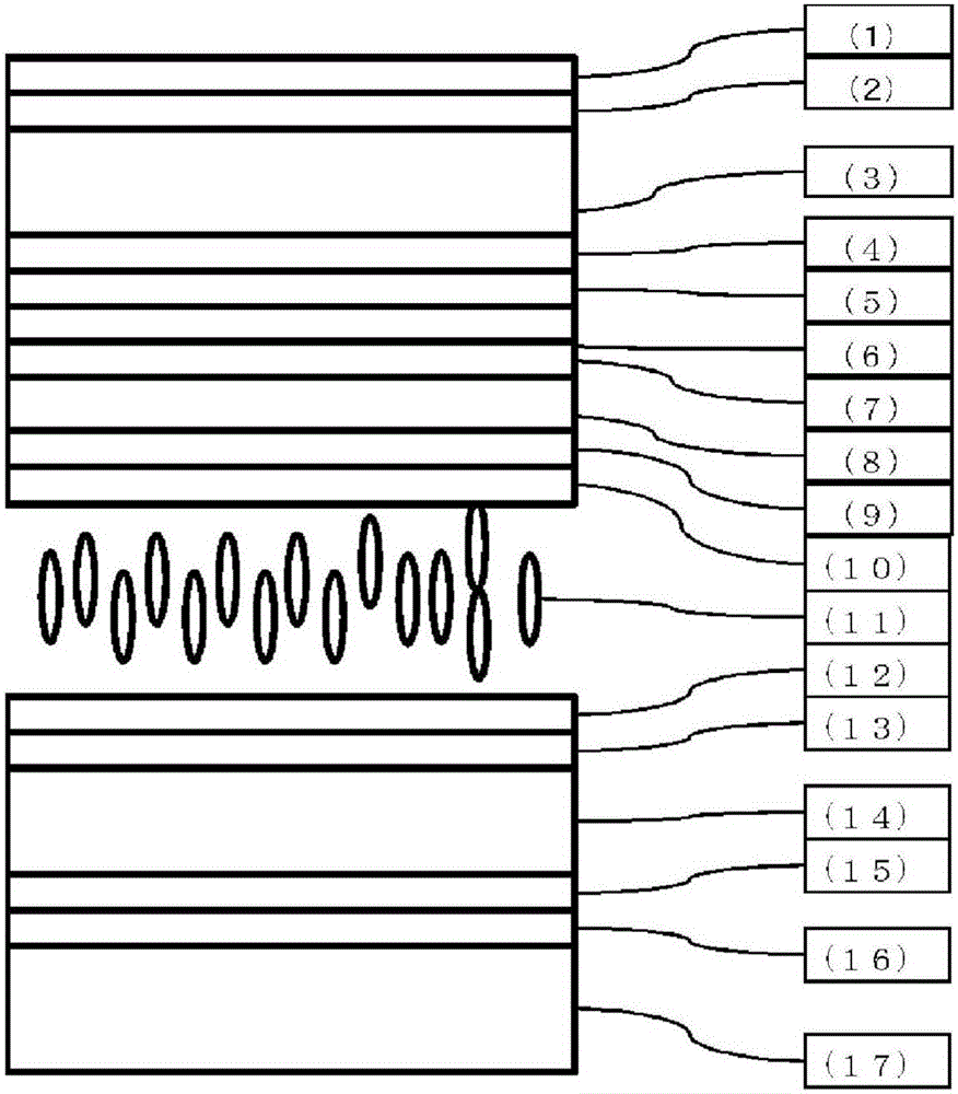
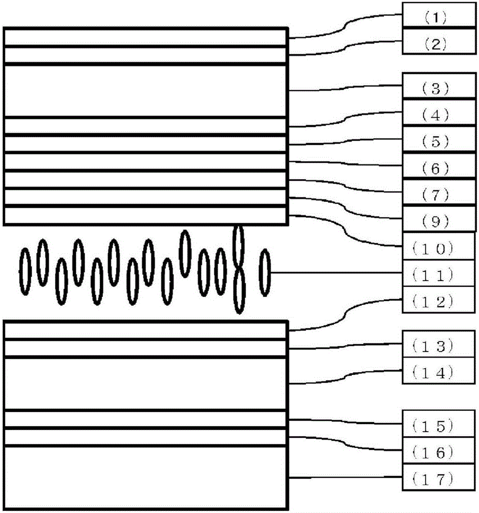
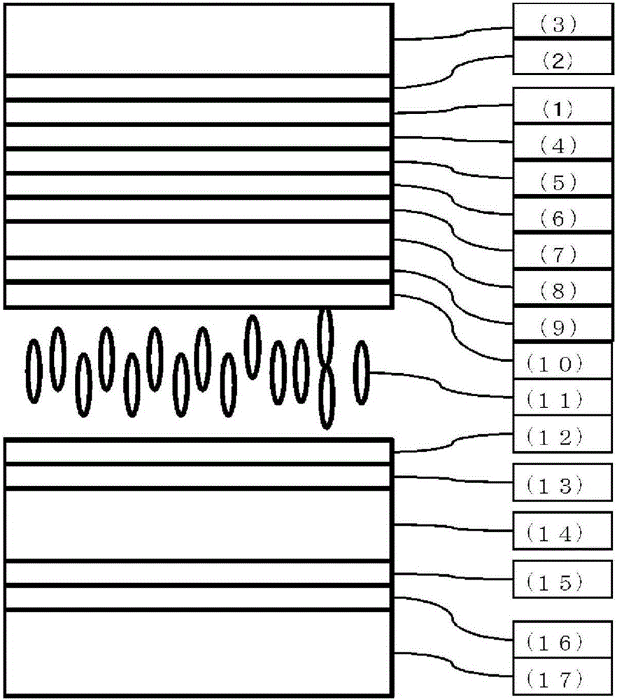
[0563] For the first translucent substrate (3), after the color filter layer (4) is installed, a horizontal alignment film (6) is formed and subjected to weak rubbing treatment. On the rubbed horizontal alignment film (6), use a spin coater to coat polymerizable liquid crystal composition 1, dry it at 80°C for 2 minutes, cool it at room temperature, and irradiate it with a high-pressure mercury lamp at 500mJ / cm 2 Ultraviolet light to make the first retardation layer (7) of the positive type A plate. Use a spin coater to coat the polymerizable liquid crystal composition 2 on the retardation layer, dry it at 80°C for 2 minutes, cool it at room temperature, and irradiate it with a high-pressure mercury lamp at 500mJ / cm 2 The ultraviolet light of making the second retardation layer (8) of negative type C plate. The transparent electrode layer (9) is vapor-deposited on the first retardation layer (7) and the second retardation layer (8) to form an alignment film (10). For the sec...

Embodiment 5~12

[0574] Except having used the liquid crystal composition and polymerizable liquid crystal composition shown below, the liquid crystal display devices of Examples 5-12 were produced similarly to Example 1, and the VHR and ID were measured. Moreover, the burn-in evaluation of this liquid crystal display device was performed. The results are shown in the table below.

[0575] [Table 7]

[0576]

[0577] [Table 8]

[0578]

[0579] [Table 9]

[0580]

[0581] The liquid crystal display devices of Examples 5 to 12 can realize high VHR and small ID. Also, in the burn-in evaluation, there was no image sticking, or even if there was, it was very small, which was at an allowable level.

Embodiment 13~24

[0583] Except having used the liquid crystal composition and polymerizable liquid crystal composition shown below, the liquid crystal display devices of Examples 13-24 were produced similarly to Example 1, and the VHR and ID were measured. Moreover, the burn-in evaluation of this liquid crystal display device was performed. The results are shown in the table below.

[0584] [Table 10]

[0585]

[0586] [Table 11]

[0587]

[0588] [Table 12]

[0589]

[0590] [Table 13]

[0591]

[0592] The liquid crystal display devices of Examples 13 to 24 can realize high VHR and small ID. Also, in the burn-in evaluation, there was no image sticking, or even if there was, it was very small, which was at an allowable level.


PUM


Abstract

The provided liquid crystal display device prevents reduction in the voltage holding ratio (VHR) of the liquid crystal layer, prevents increases in the ion density (ID), and solves the problem of display faults such as white spots, orientation irregularities, burn-in, etc. As the liquid crystal layer, this liquid crystal display device uses a liquid crystal composition which contains a liquid crystal compound of a specific structure, and, as an in-cell retardation film, uses an optically anisotropic body obtained by polymerizing a polymerizable liquid crystal composition which contains, in a specific ratio, a polymerizable liquid crystal compound of a specific structure. Because this liquid crystal display device has the feature of preventing reduction in the voltage holding ratio (VHR) of the liquid crystal layer, preventing increases in the ion density (ID) and suppressing the occurrence of display faults such as burn-in, the liquid crystal display device is particularly useful as an active matrix VA mode or PSVA mode liquid crystal display device, and can be applied to liquid crystal display devices such as liquid crystal televisions, monitors, mobile telephones and smart phones.

Description

technical field [0001] The invention relates to a liquid crystal display device. Background technique [0002] Liquid crystal display devices are used in various household electrical appliances represented by clocks and calculators, measuring instruments, panels for automobiles, word processors, electronic notebooks, printers, computers, televisions, and the like. As liquid crystal display methods, the representative methods include: TN (Twisted Nematic) type, STN (Super Twisted Nematic) type, DS (Dynamic Light Scattering) type, GH (Guest Host) type, IPS (In-Plane Switching) type, OCB (Optically Compensated Birefringence) type, ECB (Voltage Controlled Birefringence) type, VA (Vertical Alignment) type, CSH (Color Super Vertical) type, or FLC (Ferroelectric Liquid Crystal) or the like. In addition, the driving method has generally changed from the conventional static driving to multiplexing driving, and the simple matrix method, and recently the active matrix (AM) method usin...

Claims


Application Information

Patent Timeline
Patent Type & Authority Applications(China)
IPC IPC(8): G02F1/13363C09K19/12C09K19/30C09K19/38C09K19/54G02B5/30G02F1/13
CPCC09K19/24C09K19/3003C09K19/3066C09K19/322C09K19/3814C09K19/44C09K19/46C09K19/54C09K2019/0448C09K2019/0466C09K2019/122C09K2019/123C09K2019/2042C09K2019/2078C09K2019/3004C09K2019/3009C09K2019/301C09K2019/3013C09K2019/3016C09K2019/3025C09K2019/3027C09K2019/3077C09K2019/3081G02B5/3016G02F1/13363G02F1/1393C09K19/42G02F1/133565G02F1/133633
Inventor 小川真治岩下芳典山本美花桑名康弘延藤浩一初阪一辉
Owner DIC CORP
Why Eureka
Try Eureka