
Automatic gluing system and gluing method thereof

A glue application and automatic technology, applied in the field of glue application system, can solve the problems of product yield decline, alignment, and the impact of module imaging quality.

Active Publication Date: 2016-09-28
NINGBO SUNNY OPOTECH CO LTD
View PDF6 Cites 20 Cited by
  • Summary
  • Abstract
  • Description
  • Claims
  • Application Information

AI Technical Summary

Problems solved by technology

In the common manual production mode, the assembly of the mobile phone camera module is to manually adjust the positions of the lens motor module (VCM) and the photosensitive chip (SENSOR) in the camera module, so that the lenses installed in the lens assembly, The geometric optical axis center of optical lenses such as optical filters is aligned with the center of the photosensitive element of the image module. However, due to operational errors, the lens and photosensitive chip may cause the optical center of such axisymmetric optical components to appear when the system is assembled. Offset, there are positional accuracy deviations such as tilt (Tilt) and offset (Shift) between the lens and the photosensitive chip, which have a serious impact on the imaging quality of the module, resulting in a continuous decline in product yield
[0003] At present, the packaging process (COB) of the mobile phone camera module and related optical components industry generally adopts the lens mount attachment (H / A) to fix the finished product, and the lens mount attachment adopts the gel direct attachment In this way, the semi-finished lens motor module is directly attached to the semi-finished photosensitive chip, and it is often difficult to accurately align the lens assembly with the photosensitive chip in direct attachment through manual operations.
With the continuous improvement of the pixels of mobile phone camera modules, the light sensitivity of the photosensitive chip continues to increase. The offset of the optical center and the offset between the lens and the photosensitive chip have a serious impact on the imaging quality of the module, resulting in product failure. The yield rate continues to decline, and the method of direct attachment through H / A is gradually unsuitable

Method used


Image

  • Automatic gluing system and gluing method thereof
  • Automatic gluing system and gluing method thereof
  • Automatic gluing system and gluing method thereof

Examples


Embodiment Construction

[0075] According to the claims of the present invention and the content disclosed in the specification, the technical solution of the present invention is specifically described as follows.

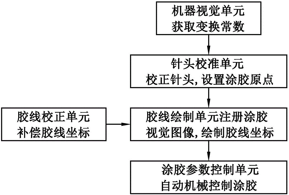
[0076] Such as figure 1 A kind of automatic gluing system shown comprises a machine vision unit, and described machine vision unit is used for obtaining conversion constant, obtains the positional relation of object pixel coordinate and machine coordinate; A needle head calibration unit, described needle head calibration unit is with For correcting the position of the needle head, the transformation constant obtained by the machine vision unit is used to set the collagen coating point of the needle head; and a glue line drawing unit, the glue line drawing unit is used to register the glue coating visual image to obtain the registration image, by The registered image draws glue line path coordinates. Therefore, the automatic gluing system adopts machine vision automatic gluing instead of ...


PUM


Abstract

The invention relates to an automatic gluing system and a gluing method thereof. The automatic gluing method comprises the following steps: S100) transformation constants of pixel coordinates and machinery coordinates of a target object can be obtained by a machinery vision unit; S200) a pin position is corrected by a pin calibration unit, a pin gluing original point is set; and S300) gluing visual image is registered by a glue line drafting unit for drafting the coordinate of the glue line path.

Description

technical field [0001] The invention relates to a gluing system, in particular to an automatic gluing system controlled by machine vision and a gluing method thereof. Background technique [0002] In the mobile phone camera module (CCM) industry, optical products are developing towards miniaturization, light weight and high precision, and the quality of optical devices is becoming more and more strictly controlled. As the pixels of mobile phone modules continue to increase, the light sensitivity is also required to continue to increase. The market is increasingly pursuing mobile phones that capture high-definition images. In the common manual production mode, the assembly of the mobile phone camera module is to manually adjust the positions of the lens motor module (VCM) and the photosensitive chip (SENSOR) in the camera module, so that the lenses installed in the lens assembly, The geometric optical axis center of optical lenses such as optical filters is aligned with the ...

Claims


Application Information

Patent Timeline
IPC IPC(8): B05C5/02B05C11/10G06T7/00
CPCB05C5/02B05C11/00
Inventor 诸庆丁小明吴林哲柯海挺
Owner NINGBO SUNNY OPOTECH CO LTD
Learn More