
An automatic cleaning system

A technology of cleaning system and combined casing, which is applied in the direction of cleaning hollow objects, cleaning methods and utensils, chemical instruments and methods, etc., can solve the problems affecting the heat exchange and production of polymerization kettles, increasing safety hazards in enterprises, and increasing enterprise costs, etc. Achieve the effect of saving manpower and material resources, no limitations, and improving production efficiency

Active Publication Date: 2019-03-05
无锡市中合科技有限公司
View PDF8 Cites 0 Cited by
  • Summary
  • Abstract
  • Description
  • Claims
  • Application Information

AI Technical Summary

Problems solved by technology

The continuous optimization of production process parameters makes the process control fluctuate. After the polymerization tank is unloaded, the residual latex loses water through the residual temperature in the tank to form hanging glue. On the inner wall of the kettle, stirring rod and accessories, it seriously affects the heat exchange and production of the polymerization kettle, reduces the production efficiency and increases the cost of the enterprise
[0003] At present, some domestic enterprises still use the soil method of personnel entering the interior of the polymerization kettle to knock and shovel the structure to clean the polymerization kettle, but in this case, the chemical substances inside the polymerization kettle will cause harm to the cleaning personnel and increase the safety hazards of the enterprise. , and the cleaning efficiency is low and the cost is high
With the continuous expansion of the sales market, it is urgent to find an effective method to deal with the problem of glue hanging in the polymerization kettle, so as not to cause greater economic losses to production and enterprises

Method used


Image

  • An automatic cleaning system

Examples


Embodiment Construction

[0016] The following will clearly and completely describe the technical solutions in the embodiments of the present invention. Obviously, the described embodiments are only some of the embodiments of the present invention, rather than all the embodiments. Based on the embodiments of the present invention, all other embodiments obtained by persons of ordinary skill in the art without making creative efforts belong to the protection scope of the present invention.

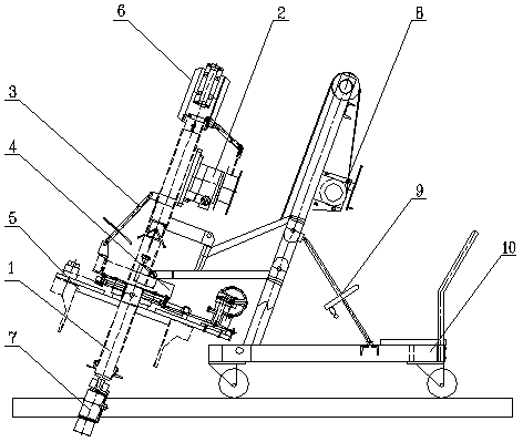
[0017] see figure 1 , the embodiment of the present invention includes:

[0018] An automated cleaning system comprising:

[0019] The cleaning assembly includes a combination sleeve 1 and a nozzle 7. The nozzle 7 is arranged at one end of the combination sleeve 1. The combination sleeve 1 is equipped with a pull rod assembly 3 and a rotating assembly 4. The pull rod assembly 3 adjusts the expansion and contraction of the sleeve in the combination sleeve 1. length, the rotating assembly 4 adjusts the horizontal and...


PUM


Abstract

The invention discloses an automatic cleaning system which comprises a cleaning assembly and a positioning assembly, wherein the cleaning assembly comprises a combination casing and a spray head; the spray head is arranged at one end of the combination casing; a rod assembly and a rotation assembly are assembled on the combination casing; the rod assembly is used for adjusting the length of a casing in the combination casing; the rotation assembly is used for adjusting the angle between the spray head and a horizontal / vertical line; the positioning assembly comprises a lifting assembly and an angle adjusting assembly; the lifting assembly is used for adjusting the height of the combination casing; the angle adjusting assembly is used for adjusting the angle of the combination casing; and both the lifting component and the angle adjusting assembly are arranged on a travelling trolley. According to the invention, cleaning is fulfilled in a mechanical way, so that the automatic cleaning system is wide in application range, free of limitation let alone influence on product quality or environment, and convenient to move and to be mounted with equipment, such as polymerization kettle, in a fitted manner; large quantities of manpower and materials can be saved during the cleaning process; the production efficiency is improved; the production cost is reduced; and the operation is easy.

Description

technical field [0001] The invention relates to the field of cleaning devices, in particular to an automatic cleaning system. Background technique [0002] With the rapid development of the global economy, in order not to be eliminated by the market, various industries have made great progress in the upgrading of equipment, automation of equipment, and de-artificialization, and they are constantly thinking about new problems Solution ideas. At present, the polymerization kettle of domestic enterprises is the main reaction place for the production of latex products such as resin, PVC, and styrene-butadiene latex. The continuous optimization of production process parameters makes the process control fluctuate. After the polymerization tank is unloaded, the residual latex loses water through the residual temperature in the tank to form hanging glue. On the inner wall of the kettle, the stirring rod and accessories, the heat exchange and production of the polymerization kettle...

Claims


Application Information

Patent Timeline
Patent Type & Authority Patents(China)
IPC IPC(8): B08B9/093
CPCB08B9/0936
Inventor 季亮余煜唐琪良张晓军
Owner 无锡市中合科技有限公司
Learn More