Self-aligning interface apparatus for use in testing electrical devices

A technology for automatic alignment and interface devices, applied in the direction of electronic circuit testing, measuring devices, measuring device casings, etc., can solve problems such as limited equipment achievements, tedious procedures, and time-consuming

Inactive Publication Date: 2002-06-12
TENSOLITE CO
View PDF1 Cites 9 Cited by
  • Summary
  • Abstract
  • Description
  • Claims
  • Application Information

AI Technical Summary

Problems solved by technology

Therefore, these procedures are tedious and time consuming
[0003] Although there are many devices that can quickly connect individual cables to the interface, s...

Method used


Image

  • Self-aligning interface apparatus for use in testing electrical devices
  • Self-aligning interface apparatus for use in testing electrical devices
  • Self-aligning interface apparatus for use in testing electrical devices

Examples


Embodiment Construction

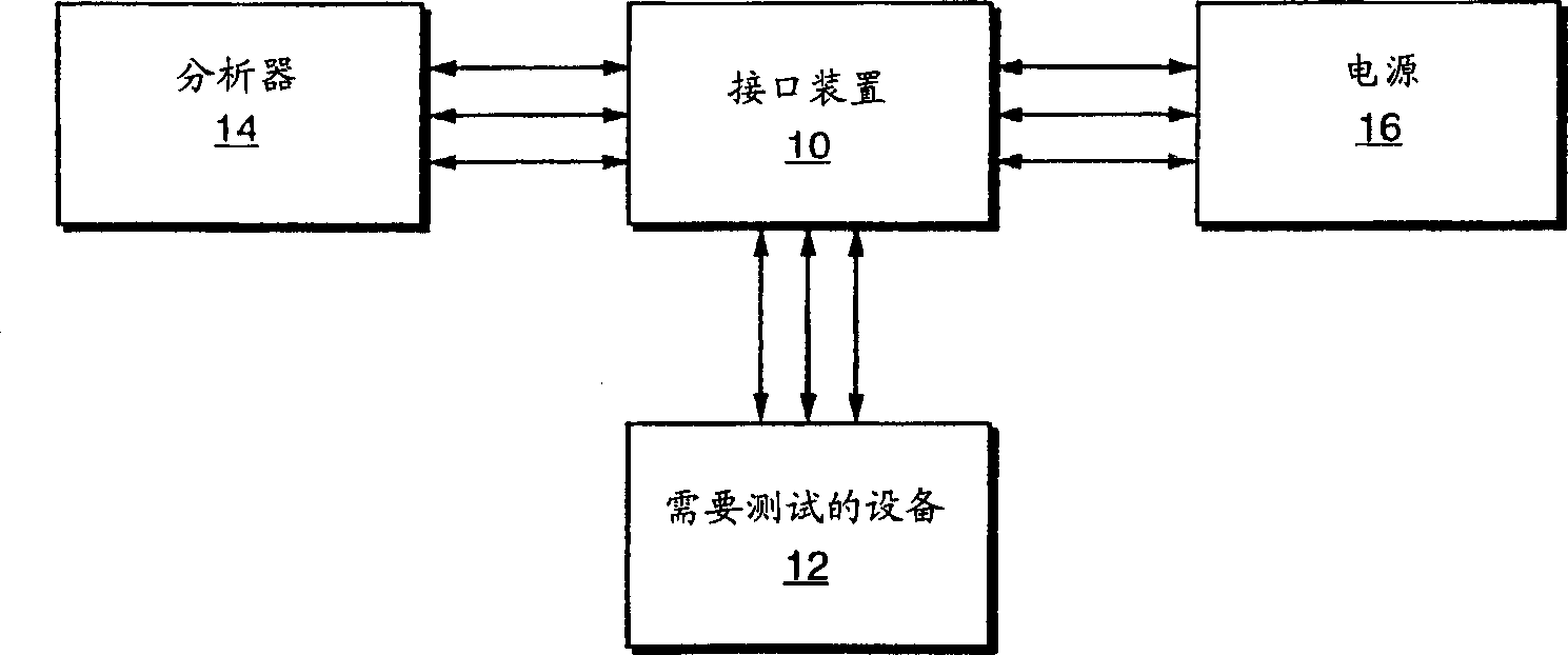
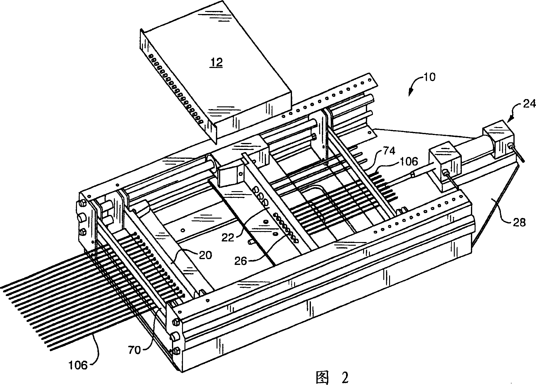
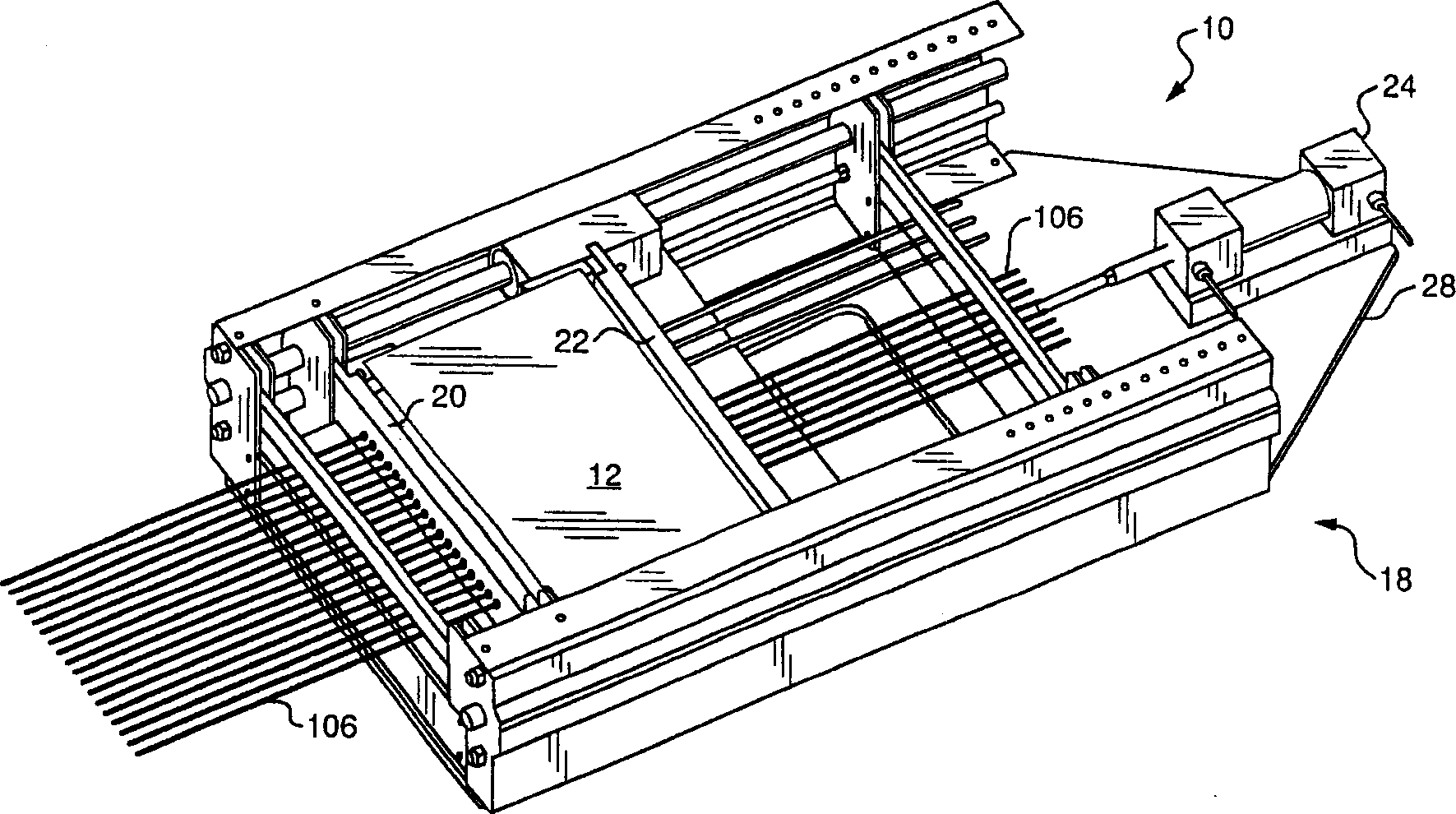
[0019] Refer now to the attached drawings, especially figure 1 To FIG. 5, the interface device 10 involved in the present invention is shown. The interface device 10 can interconnect a device 12 that needs to be tested with an analyzer 14 and a power supply 16 for testing the device that needs to be tested. Together. As will be described in detail below, the interface device 10 includes a fixing device 18, a pair of interface elements 20 and 22, and a pushing assembly 24. The interface elements 20 and 22 are equipped with a plurality of auto-aligning coaxial connectors 26, and the positions of these auto-aligning coaxial connectors are basically aligned with the matching connectors 27 on the device 12. The interface device 10 shown in FIG. 2 is in its open position to receive the device 12. image 3 The interface device 10 shown in is in the closed position and the connector 27 is connected to the auto-aligned coaxial connector 26. The pushing assembly 24 is installed on the base...


PUM


Abstract

An interface apparatus (10) having a plurality of self-aligning coaxial connectors (26) for substantially simultaneous interconnections with a plurality of connectors (27) on a unit under test (12) includes a base member (28), a first interface (20) and a second interface (22). At least one of the first (20) and second (22) interfaces is slidably movable on the base member (28) and has a plurality of self-aligning coaxial connectors (26) to interconnect with the plurality of connectors (27) on the unit under test (12). An urging means (24) is provided for moving the interfaces (20 and 22) so that the self-aligning coaxial connectors (26) are moved into mating engagement with the plurality of connectors (27) on the unit under test (12) that is between the interfaces (20 and 22). The self-aligning connectors (26) are provided with cables (106) that are configured to be connected to an analyzer (14) and a supply (16) for testing the unit under test (12).

Description

Technical field [0001] The invention relates to an interface device, in particular to an automatic alignment interface device used in electronic equipment testing, especially in microwave equipment testing. Background technique [0002] Electronic testing of microwave equipment, including the use of a variety of industrial standards and specific-purpose microwave interfaces, such as Type N, Type F, SMA TNC and BNC, usually requires a manual method to connect each individual test cable and each The interfaces are connected together. Therefore, these procedures are tedious and time-consuming. [0003] Although there are a variety of devices that can quickly connect a separate cable to the interface, such devices have limitations and shortcomings and each test cable must be connected to the interface separately. Therefore, the results of these devices are very limited. [0004] The self-aligning coaxial cable connector has been designed, which can interconne...

Claims


Application Information

Patent Timeline
IPC IPC(8): G01R1/04G01R31/28H01R13/631H01R24/40H01R43/26
CPCH01R24/40G01R31/2822H01R2103/00H01R13/6315G01R1/0416H01R43/26
Inventor 詹姆斯·J·克里根小弗兰克·K·波特
Owner TENSOLITE CO
Why Eureka
Try Eureka