Process for grinding double bevel edges of glass

A double-bevel, glass technology, used in grinding machines, grinding heads, manufacturing tools, etc., can solve the problems of low production efficiency, small amount of chamfer grinding, glass deformation, etc., to save cost, improve work efficiency, reduce Effects of Correction Steps

Active Publication Date: 2016-09-28
TIANJIN NORTH GLASS IND TECHN
View PDF11 Cites 0 Cited by
  • Summary
  • Abstract
  • Description
  • Claims
  • Application Information

AI Technical Summary

Problems solved by technology

The processing of the existing glass double bevel generally means that the two bevels are located in the same direction of the bottom surface, that is, the two bevels are facing upwards, and the cross section of the glass is trapezoidal. The glass double bevel edge grinding machine on the market can easily realize this. Purpose; but for the direction of the two hypotenuses not in the same direction, that is, one hypotenuse is facing up and the other is facing down, the processing method of the cross-section of the glass is a flat quadrilateral is only unilateral processing, and then unilaterally after turning over Processing, this processing method requires re-adjustment and calibration of the machine, which is time-consuming and labor-intensive, and the production efficiency is very low
The existing double-bevel edge grinding machine also has a chamfer grinding head for grinding the chamfer, but the amount of chamfer grinding is small, which cannot meet the processing requirements of the bevel, and even if the chamfer grinding head is directly replaced with With the lower bevel grinding wheel, one side of the glass is processed with the lower bevel, and the opposite side is processed with the upper bevel, which will inevitably form a seesaw shape, so that the glass on the side of the upper bevel is easy to lift up, causing glass deformation, and the lower bevel There is also a lack of cooling facilities during the edging process, and the conventional water pipe cooling cannot meet the cooling requirements for lower beveled edging

Method used


Image

  • Process for grinding double bevel edges of glass
  • Process for grinding double bevel edges of glass

Examples


Embodiment Construction

[0017] The present invention will be further described in detail below in conjunction with the examples.

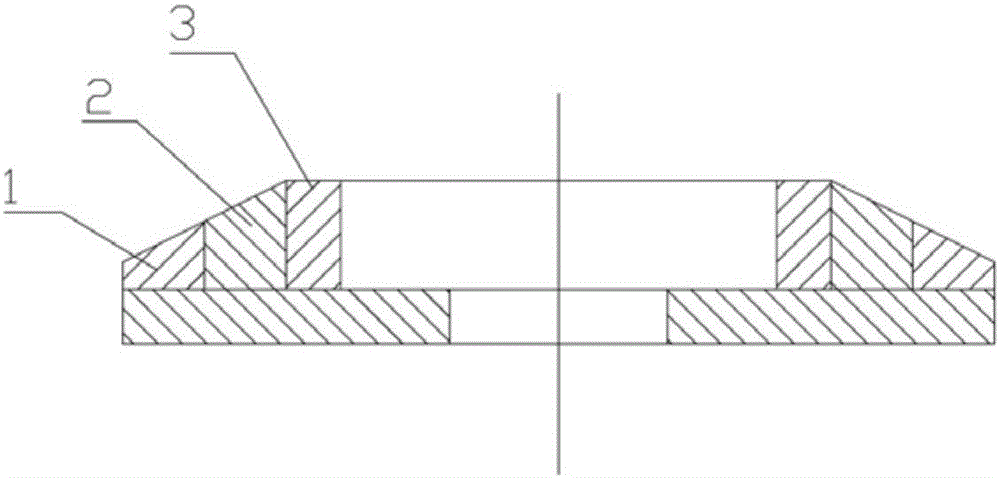
[0018] Glass double bevel edge grinding, the finished glass section see figure 1 .

[0019] Equipment and process transformation:

[0020] 1. Modification of edging grinding head

[0021] Install multiple beveled grinding wheels on the same motor, and the large circle of the outer ring is a small mesh grinding wheel, and then increase the mesh number successively, which can be three or four, figure 2 In the middle, three grinding wheels with different mesh numbers are installed on the same motor, the outer ring 1 is 100 mesh, the middle 2 is 140 mesh, and the inner ring 3 is 240 mesh.

[0022] 2. Change the chamfering grinding head to edging grinding head

[0023] If there is a chamfering grinding head under the glass on one side of the original double-sided edging machine, replace one side with an edging grinding head, if not, install it under the glass. After modi...


PUM


Abstract

The invention relates to a process for grinding double bevel edges of glass. The cross section of the glass is a parallelogram, namely one side is the upper bevel edge while the other side is the lower bevel edge. The process is characterized in that a lead angle grinding head, located below the glass, of an edge grinding machine is replaced with an edge grinding head identical with an edge grinding head on the upper opposite side of the glass, and part of a grinding wheel of the grinding head below the glass is soaked in water; meanwhile, single sliding blocks, connected with steel spring plates correspondingly, in a clamp are replaced with an integrated sliding block; and the upper edge grinding head and the lower edge grinding head are used for simultaneously grinding the two edges of the glass. According to the process, by modifying existing processes and equipment, the upper bevel edge and the lower bevel edge are ground simultaneously; meanwhile, the edge grinding heads are modified, so that the equipment manufacturing cost is reduced; and moreover, a correction step is omitted during operation, so that the working efficiency is improved.

Description

technical field [0001] The invention relates to the technical field of glass processing, in particular to a high-efficiency glass double-bevel edge grinding process. Background technique [0002] The glass edging machine mainly realizes the grinding and polishing of glass through the grinding head motor and grinding wheel. Ordinary single-sided / double-sided edging machines can realize rough grinding, fine grinding and polishing at one time. Customers can choose different grinding wheels according to their processing requirements. Glass edging generally has straight edges and beveled edges. The main purpose of grinding into beveled edges is to look good, or for splicing for special purposes, and straight beveled edges are the most common design. The processing of the existing glass double bevel generally means that the two bevels are located in the same direction of the bottom surface, that is, the two bevels are facing upwards, and the cross section of the glass is trapezoi...

Claims


Application Information

Patent Timeline
Patent Type & Authority Applications(China)
IPC IPC(8): B24B9/10B24B41/00B24B55/02
CPCB24B9/10B24B41/002B24B55/02
Inventor 张东升全晓萍
Owner TIANJIN NORTH GLASS IND TECHN
Why Eureka
Try Eureka