Guided anti-climbing energy-absorbing device for rail vehicle and rail vehicle with the device

An energy-absorbing device and guided technology, which is applied in the direction of railway vehicle wheel guards/buffers, transportation and packaging, railway car body parts, etc., can solve the problem of failure to ensure anti-climbing characteristics, difficulty in taking into account vertical and lateral bearing capacity, Dissipate impact kinetic energy and other issues to achieve the effect of simple structure and manufacturing process, stable and controllable deformation, and strong vertical and lateral bearing capacity

Active Publication Date: 2018-03-20
CENT SOUTH UNIV
View PDF6 Cites 1 Cited by
  • Summary
  • Abstract
  • Description
  • Claims
  • Application Information

AI Technical Summary

Problems solved by technology

[0006] Usually, ordinary anti-climbing energy-absorbing devices are generally equipped with anti-climbing teeth at the front end of the energy-absorbing structure. We generally require the energy-absorbing structure to undergo orderly and controllable plastic deformation in the longitudinal direction to dissipate the impact kinetic energy, which is difficult to balance The whole device achieves good vertical and lateral bearing capacity
Therefore, while ensuring that the entire structure has good energy absorption characteristics, it does not guarantee that the entire structure has good anti-climbing characteristics.

Method used


Image

  • Guided anti-climbing energy-absorbing device for rail vehicle and rail vehicle with the device
  • Guided anti-climbing energy-absorbing device for rail vehicle and rail vehicle with the device
  • Guided anti-climbing energy-absorbing device for rail vehicle and rail vehicle with the device

Examples


Embodiment Construction

[0029] In order to facilitate the understanding of the present invention, the present invention will be described in detail below with reference to the drawings and preferred embodiments of the specification, but the protection scope of the present invention is not limited to the following specific embodiments.

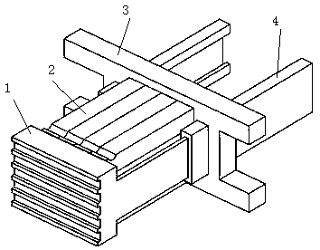
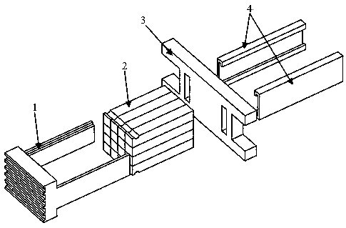
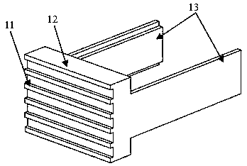
[0030] Such as Figure 1~Figure 8 As shown, an embodiment of the guided anti-climbing energy absorbing device of the present invention includes an anti-climbing guide component 1 and an energy absorbing component 2. The anti-climbing guide component 1 includes a front baffle 12, two longitudinal guides 13, and two The longitudinal guide rail 4 and the rear baffle 3 for vertical load bearing. The front part (impact end) of the front baffle 12 is provided with anti-creep teeth 11; two longitudinal guides 13 are fixed on the rear part of the front baffle 12 (non-impact On both sides of the end), two longitudinal guide rails 4 are fixed on the underframe of the car body, and...


PUM


Abstract

The invention discloses a guiding-type anti-climbing energy-absorbing device for a rail vehicle. The guiding-type anti-climbing energy-absorbing device comprises an anti-climbing guiding assembly and an energy absorbing assembly. Anti-climbing teeth are arranged at the front end of the anti-climbing guiding assembly, the anti-climbing guiding assembly comprises a front baffle, two longitudinal guiding pieces fixed to the two sides of the front baffle, two longitudinal guide rails fixed to a vehicle body chassis and used for guiding and transverse bearing and a back baffle with the top fixed to the vehicle body chassis and used for vertical bearing, the anti-climbing teeth are arranged at the front portion of the front baffle, the back baffle is arranged behind the front baffle in parallel, the front ends of the guide rails penetrate through the back baffle and are fixedly connected with the back baffle, the back ends of the guiding pieces are seamlessly inserted into the corresponding guide rails, a cavity is defined by the front baffle, the back baffle and the two guiding pieces, the energy absorbing assembly is embedded into the cavity, and the two ends of the energy absorbing assembly are fixed on the front baffle and the back baffle respectively. The guiding-type anti-climbing energy-absorbing device is simple in structure and convenient to install, vertical bearing capacity and transverse bearing capacity are achieved, and orderly and controllable plastic deformation can be generated in the longitudinal impacting direction. Two anti-climbing energy-absorbing devices are arranged at the front end of the vehicle body chassis of the rail vehicle.

Description

Technical field [0001] The present invention relates to the technical field of passive safety protection for rail vehicles, in particular to a guided anti-climb energy absorbing device for rail vehicles and a rail vehicle with the device. Background technique [0002] With the rapid development of the railway industry, the speed of rail transportation is getting faster and faster, and at the same time, the safety of rail vehicles is getting more and more attention. If a vehicle accident occurs, the passive safety protection measures of the vehicle itself become particularly important. [0003] The rail vehicle runs on a dedicated track, so it has good guidance and can avoid traffic accidents such as rubbing against other vehicles like other vehicles. In addition, the railway system is equipped with an advanced dispatching system and communication system, which makes the probability of accidents in the railway system far less than other vehicles. However, due to the large number o...

Claims


Application Information

Patent Timeline
Patent Type & Authority Patents(China)
IPC IPC(8): B61F19/04
CPCB61F19/04
Inventor 谢素超梁习锋高广军许平姚松鲁寨军彭勇
Owner CENT SOUTH UNIV
Why Eureka
Try Eureka