Pile-anchor-combing-type foundation-basis compression-resistance static-load test system
A stack-anchor combined, compressive and static load-resistant technology, which is applied in the testing of infrastructure, infrastructure engineering, construction, etc., can solve problems such as the limitation of supporting walking ability, increase manufacturing cost, reduce practicability, etc., and reduce transportation capacity. requirements, manufacturing cost saving, cost saving effect
- Summary
- Abstract
- Description
- Claims
- Application Information
AI Technical Summary
Problems solved by technology
Method used
Image

Examples
Embodiment 1
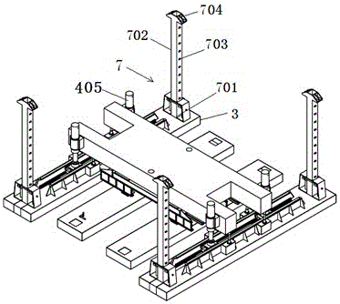
[0039] Such as figure 1 , 2 As shown, the anchor pile mechanism 7 described in Embodiment 1 includes an anchor pile 702 and an anchor pile clamping accessory, and an anchor pile through hole 701 is set on the outer ship 3, and the anchor pile clamping accessory is fixed on the outer surface above the anchor pile through hole 701. On the ship 3, the anchor pile 702 is vertically installed in the anchor pile through hole 701, the two side walls of the anchor pile 702 are provided with raised stoppers 703 at intervals, the top of the anchor pile 702 is provided with a pile cap 704, and the anchor pile clamping accessories include brackets And the pressure plate 706 that is located on both sides of the anchor pile symmetrically and rotates around the rotating shaft 705 supported by the bracket. The inner side of the pressure plate 706 is close to the anchor pile against the stopper 703, and the upper side of the pressure plate 706 is connected with a return spring 707. Insertion ...
Embodiment 2
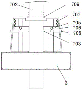
[0042] Such as image 3 As shown, the anchor pile through hole 701 is set on the inner ship 3, and the anchor pile clamping accessories are fixed on the inner ship 3 above the anchor pile through hole 701 around the top, and the rest are the same as in embodiment 1.
[0043] Brief description of the working method: After the system reaches the designated detection position, the anchor pile 702 is pressed in and pulled out through the expansion and contraction of the outer ship lifting cylinder 405. Taking the pressing in as an example, as shown in image 3 , Figure 4 As shown, insert the limit plug 708 into the lower part of the pressure plate 706 (the limit plug needs to be inserted into the upper part of the pressure plate when the anchor pile is pulled out), the outer ship support system, the outer ship lifting cylinder 405 will lift the inner ship hull, and the anchor The pile 702 is affected by its own weight and does not move accordingly. The bottom of the pressure pla...
Embodiment 3
[0045] Such as Figure 4 , Figure 5 As shown, the anchor pile mechanism 7 includes an anchor pile 702, an anchor pile clamping accessory and an anchor pile oil cylinder 710. The anchor pile clamping accessory is connected to the two ends of the pressure-bearing platform 1 through the anchor pile oil cylinder 710, and the anchor pile 702 is installed vertically. Through the anchor pile clamping accessories, the two side walls of the anchor pile 702 are provided with raised stoppers 703 at intervals, and the top of the anchor pile 702 is provided with a pile cap 704. Pressing plate 706, the inner side of the pressing plate 706 is set as a slope surface, the bottom edge is close to the anchor pile against the stopper 703, and the outer side is connected with a return spring (707) in a parallel direction. out.
[0046] Brief description of the working method: After the system reaches the designated detection position, the anchor pile 702 is pressed in and pulled out through the...
PUM
 Abstract
Description
Claims
Application Information
 - R&D
- Intellectual Property
- Life Sciences
- Materials
- Tech Scout
- Unparalleled Data Quality
- Higher Quality Content
- 60% Fewer Hallucinations
Browse by: Latest US Patents, China's latest patents, Technical Efficacy Thesaurus, Application Domain, Technology Topic, Popular Technical Reports.
© 2025 PatSnap. All rights reserved.Legal|Privacy policy|Modern Slavery Act Transparency Statement|Sitemap|About US| Contact US: help@patsnap.com