Transfer ring beam for concrete cylinder and steel cylinder combined tower and construction method thereof

A technology of concrete and ring beams, which is applied in the assembly of wind turbines, the configuration of installation/supporting wind turbines, wind power generation, etc., can solve the problems of difficulty in guaranteeing construction quality, increasing the amount of concrete work, local stress concentration, etc., and achieve saving and The effect of the amount of prestressed steel, the uniformity of stress distribution, and the reduction of section size

Active Publication Date: 2016-09-28
CHINA AVIATION PLANNING & DESIGN INST GRP
View PDF3 Cites 12 Cited by
  • Summary
  • Abstract
  • Description
  • Claims
  • Application Information

AI Technical Summary

Problems solved by technology

However, the dispersion effect of the steel backing plate is poor, and there will still be obvious local stress concentration on the top of the concrete tower, and the construction process of the steel backing plate is complicated, and the construction quality on site is difficult to guarantee
[0003] In the structure where the steel backing plate is switched, under the action of the main bending moment of the tower, the bottom flange of the steel tower section will be partially separated from the steel backing plate in the tension area to cause warping. In order to reduce the warping, it is necessary to apply a large additional The prestress tightly presses the flange on the transition steel backing plate. This additional prestress will greatly increase the design value of the compressive stress of the concrete section, forcing the thickness of the concrete tower section to increase, increasing the amount of concrete work.

Method used


Image

  • Transfer ring beam for concrete cylinder and steel cylinder combined tower and construction method thereof

Examples


Embodiment Construction

[0031] In order to make the technical means, innovative features, objectives and effects achieved by the present invention easy to understand, the present invention will be further described below in conjunction with the accompanying drawings.

[0032] The examples described here are specific specific implementations of the present invention, and are used to illustrate the concept of the present invention. They are all explanatory and exemplary, and should not be construed as limiting the implementation of the present invention and the scope of the present invention. In addition to the embodiments described here, those skilled in the art can also adopt other obvious technical solutions based on the claims of the application and the contents disclosed in the description, and these technical solutions include adopting any obvious changes made to the embodiments described here. Replacement and modified technical solutions.

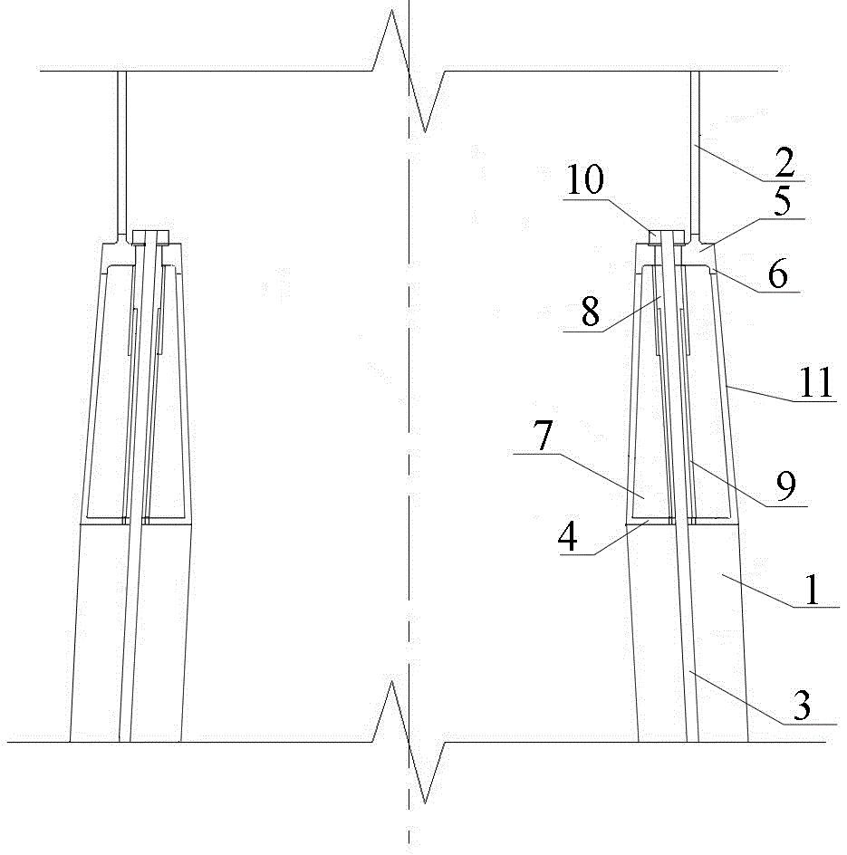
[0033] 1) The flange 5 at the bottom of the steel tower...


PUM


Abstract

The invention provides a transfer ring beam for a concrete cylinder and steel cylinder combined tower and a construction method thereof. The transfer ring beam is arranged between the concrete tower cylinder and the steel tower cylinder and is formed by defining an annular bottom plate horizontally arranged, ring beam webs fixe to the annular bottom plate and a flange covering the top of the ring beam webs. The annular bottom plate serves as a lower flange plate of an annular box girder, and the flange serves as an upper flange plate. The ring beam web is welded to the annular bottom plate. The upper surface of the flange is fixed to the steel tower cylinder. The positions, corresponding to the two ring beam webs, of the lower surface of the flange protrude to form a protruding opening. The protruding opening is correspondingly connected with the top ends of the wing beam webs. The annular bottom plate and the flange are provided with prestressing tendon preformed holes correspondingly. Internal prestressing tendons penetrate through the concrete tower cylinder and the transfer ring beam from bottom to top and then are fixed through prestressed anchorage devices. By adopting the transfer ring beam, extra prestressing pressure in the concrete section of the tower cylinder can be reduced, the section thickness of the concrete tower cylinder can be decreased, concrete material consumption is reduced, and the hoisting and installation difficulty of the precast concrete tower cylinder is lowered.

Description

technical field [0001] The invention relates to the construction field of power generation towers, in particular to a conversion ring beam used for a tower combined with a concrete cylinder and a steel cylinder and a construction method thereof. Background technique [0002] The transition between the prestressed concrete tower and the steel cylinder is subject to complex forces. Since the section thickness of the steel cylinder is very small, while the section thickness of the prestressed concrete cylinder is relatively large, it is very obvious that the concrete at the junction of the two bears local concentrated loads. Therefore, the existing method is to set up steel transition pads to gradually disperse the concentrated load transmitted from the steel cylinder to the concrete section. pressure. However, the dispersion effect of the steel backing plate is poor, and there will still be obvious local stress concentration on the top of the concrete tower, and the construct...

Claims


Application Information

Patent Timeline
Patent Type & Authority Applications(China)
IPC IPC(8): F03D13/20F03D13/10
CPCF05B2230/232Y02E10/72Y02E10/728
Inventor 张曼生葛家琪张国军王树张奇铭
Owner CHINA AVIATION PLANNING & DESIGN INST GRP
Why Eureka
Try Eureka