
Rigid oil guiding device capable of achieving reciprocate motion

An oil guide device and reciprocating movement technology, applied in fluid pressure actuating devices, mechanical equipment, etc., can solve problems such as hose drooping, inconvenient use, and affecting the normal operation of the system

Active Publication Date: 2016-09-28
TIANJIN URANUS HYDRAULIC MACHINERY
View PDF7 Cites 0 Cited by
  • Summary
  • Abstract
  • Description
  • Claims
  • Application Information

AI Technical Summary

Problems solved by technology

However, during the movement of the platform, the rubber hose will be continuously straightened and bent, which will affect the service life of the rubber hose; further, when the displacement of the moving parts is large, the rubber hose will sag and may interfere with other parts of the system, even Affect the normal work of the system and cause inconvenience in use

Method used


Image

  • Rigid oil guiding device capable of achieving reciprocate motion
  • Rigid oil guiding device capable of achieving reciprocate motion
  • Rigid oil guiding device capable of achieving reciprocate motion

Examples


Embodiment Construction

[0013] Below in conjunction with the examples, the present invention is further described, the following examples are illustrative, not limiting, and the protection scope of the present invention cannot be limited by the following examples.

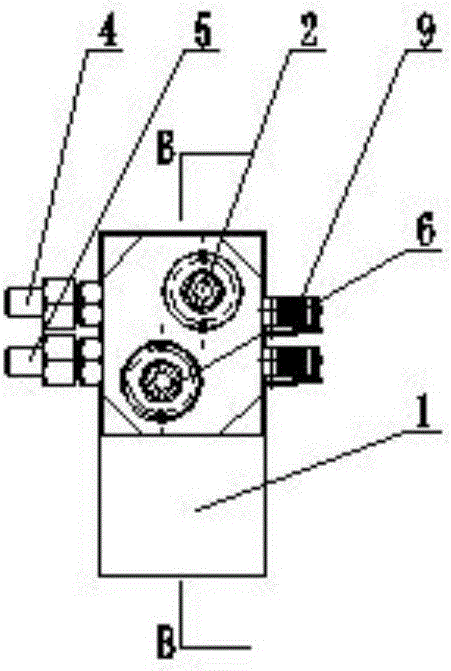
[0014] A rigid oil guiding device capable of reciprocating movement. The innovation of the present invention is that it includes two oil pipes arranged in parallel at intervals. One end of the two oil pipes is fixedly installed with a fixed bracket 1, and the other end of the two oil pipes An external oil guide bracket 8 is connected and installed through the joint 7, and an oil passage 13 is arranged inside the external oil guide bracket to communicate with the external hydraulic station. A movable box 3 is installed slidingly outside the two oil pipes, and the movable box is located outside the two oil pipes. A cavity 11 is respectively made in the space of the two oil pipes. One of the two oil pipes is the oil inlet pipe 2, and the othe...


PUM


Abstract

The invention relates to the field of hydraulic device manufacturing, in particular to a rigid oil guiding device capable of achieving reciprocate motion. The rigid oil guiding device comprises two oil tubes arranged in parallel in a spaced mode. The ends of one sides of the two oil tubes and a fixing support are fixedly installed. The ends of the other sides of the two oil tubes are communicated with an external oil guiding support. The external oil guiding support is communicated with an external hydraulic station. The outer sides of the two oil tubes are provided with a movable box in a sliding mode. The portions, on the outer sides of the two oil tubes, inside the movable box are each provided with a cavity. One oil tube is an oil inlet tube, and the other oil tube is an oil return tube. The middles of the side walls of the oil inlet tube and the oil return tube are each provided with an oil tube port. The oil tube ports are communicated with the corresponding cavities respectively. Two oil ports are manufactured in the side wall of the movable box. The oil tube port communicated with the oil inlet tube is a movable oil inlet, and the oil tube port communicated with the oil return tube is a movable oil return port. The movable oil inlet and the movable oil return port are used for being communicated with external equipment to form a loop.

Description

technical field [0001] The invention relates to the field of hydraulic device manufacturing, in particular to a reciprocatingly movable rigid oil guiding device. Background technique [0002] For equipment or work platforms that need to be moved, the distance between the moving part and the fixed frame of the equipment is constantly changing. If the moving part needs various fluids and pressure media such as hydraulic oil, it can only be connected through flexible hoses to complete Transport of fluid media. However, during the movement of the platform, the rubber hose will be continuously straightened and bent, which will affect the service life of the rubber hose; further, when the displacement of the moving parts is large, the rubber hose will sag and may interfere with other parts of the system, even Affect the normal work of the system and cause inconvenience in use. Contents of the invention [0003] The object of the present invention is to overcome the deficiencie...

Claims


Application Information

Patent Timeline
Patent Type & Authority Applications(China)
IPC IPC(8): F15B15/00
CPCF15B15/00F15B2215/00
Inventor 李晓龙王超光于安才刘兵陶娟
Owner TIANJIN URANUS HYDRAULIC MACHINERY
Learn More