Stent implant driving mechanism and medical stent placement device

A technology of driving mechanism and implantation device, applied in the field of medical devices

Pending Publication Date: 2020-06-19
JIANGSU VEDKANG MEDICAL SCI & TECH
View PDF0 Cites 2 Cited by
  • Summary
  • Abstract
  • Description
  • Claims
  • Application Information

AI Technical Summary

Problems solved by technology

[0004] The second object of the present invention is to provide a medical stent implantation device to solve the technical problem of improving the flexibility of the operation process of stent implantation

Method used


Image

  • Stent implant driving mechanism and medical stent placement device
  • Stent implant driving mechanism and medical stent placement device
  • Stent implant driving mechanism and medical stent placement device

Examples


Embodiment 1

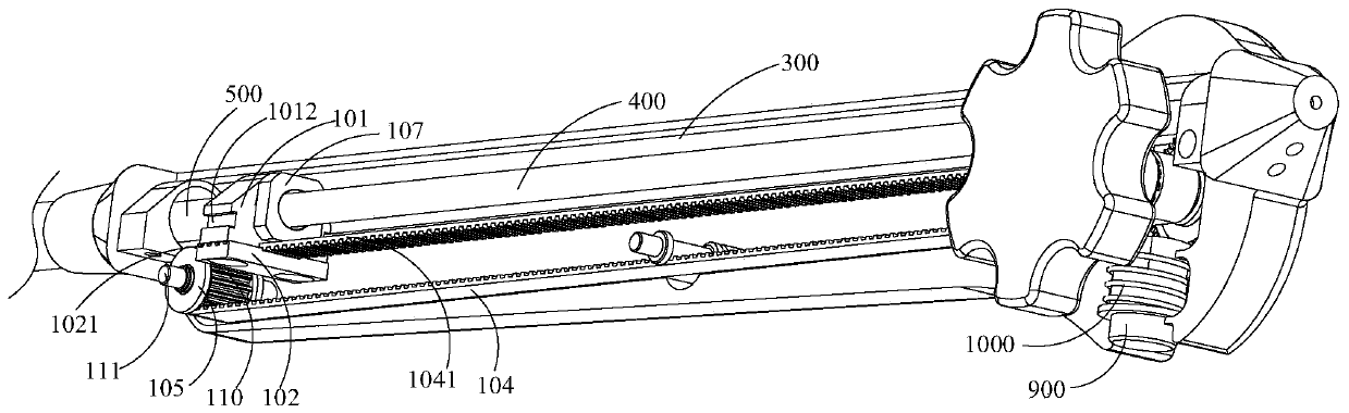
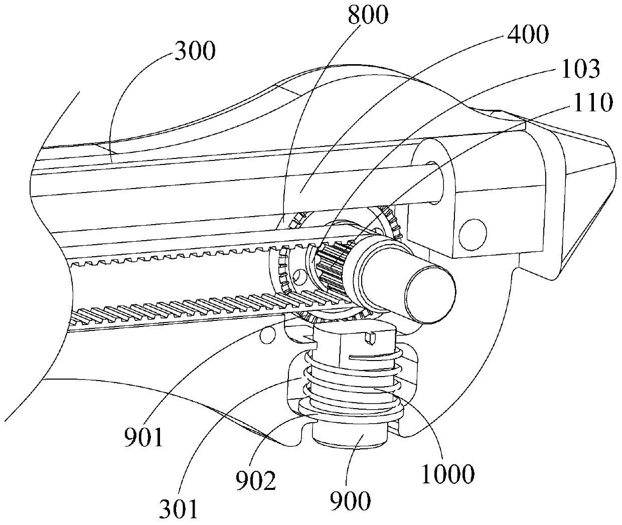
[0058] Such as Figure 1 to Figure 11 As shown, this embodiment provides a driving mechanism for a stent implanter, which is suitable for medical stent implantation devices, including: an outer tube clamping mechanism suitable for clamping the outer tube 500 and a shaft suitable for driving the outer tube 500 to move Move the drive mechanism. The outer tube clamping mechanism includes an outer tube 101 fixedly fitted on the outer tube 500 , and a pressing block 102 connected with the outer tube 101 . The shaft-moving drive mechanism includes a transmission assembly that cooperates with the pressing block 102 to drive the pressing block 102 to move, and a power part connected to the transmission assembly; that is, the power part is suitable for driving the transmission assembly to drive the pressing block 102 to move while realizing the outer tube The synchronous movement of 500; the transmission assembly includes an annular synchronous structure, and a passive runner 105 and ...

Embodiment 2

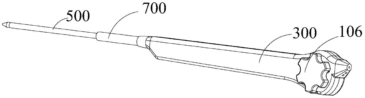
[0065] Such as Figure 1 to Figure 16 As shown, on the basis of the driving mechanism of the stent implanter in Embodiment 1, this embodiment provides a medical stent implantation device, including: a middle tube 200, an operating handle 300 fixedly connected to the middle tube 200, and a The inner tube 400 inside the middle tube 200, and the outer tube 500 located outside the middle tube 200; wherein the operating handle 300 is provided with the driving mechanism of the stent implanter in Embodiment 1; The outer tube 101 ; and the driving mechanism of the stent implanter is suitable for driving the outer tube 500 to move linearly and reciprocatingly along the axis of the inner tube 400 ; a stent 600 is provided between the inner tube 400 and the outer tube 500 . In addition, the operating handle 300 is also fixedly connected with a handle tube 700 sleeved on the outside of the outer tube 500 .

[0066] In simple terms, the inner tube 400, the middle tube 200, the handheld tu...


PUM


Abstract

The invention discloses a stent implant driving mechanism and a medical stent placement device. The stent implant driving mechanism comprises an outer pipe clamping mechanism suitable for clamping anouter pipe and a shaft displacement driving mechanism suitable for driving the outer pipe to move, wherein the outer pipe clamping mechanism comprises an outer sleeve pipe fixedly arranged on the outer pipe in a sleeving manner, and a pressing block connected with the outer sleeve pipe; the shaft displacement driving mechanism comprises a transmission assembly which cooperates with the pressing block to be suitable for driving the pressing block to move, and a power part which is connected with the transmission assembly; the power part is suitable for driving the transmission assembly to drivethe pressing block to move, and besides, simultaneous movement of the outer pipe is realized; the transmission assembly comprises an annular simultaneous structure and a driven rotating wheel and a driving rotating wheel which are in adapting with the annular simultaneous structure; and the driving rotating wheel and the power part are in adapting to be suitable for the power part to drive the driving rotating wheel to rotate. According to the medical stent placement device, the flexibility of the stent placement operation process can be improved.

Description

technical field [0001] The invention relates to the technical field of medical devices, in particular to a driving mechanism of a stent implanter and a medical stent implantation device. Background technique [0002] There are two main operation modes for stent release and implantation routinely used in the prior art: one is the traditional linear motion push type release stent operation mode, the doctor holds the instrument with one hand, and pulls the release device with the other hand to release the stent with linear motion. During the release process of the stent, the doctor needs to control two handles (fixed handle and moving handle) at the same time. , Excessive operating force will easily cause the outer tube to retreat far, and the stent will be released excessively, causing the stent to be released at the wrong position. Secondly, because the doctor operates with both hands, there is relative movement between the two hands, and the fixed position of the fixed handl...

Claims


Application Information

Patent Timeline
Patent Type & Authority Applications(China)
IPC IPC(8): A61F2/966A61F2/97
CPCA61F2/966A61F2/97
Inventor 陶凯田立敏
Owner JIANGSU VEDKANG MEDICAL SCI & TECH
Why Eureka
Try Eureka