Color filter substrate and display panel

A technology of color film substrate and stereoscopic display, which is applied in the fields of instruments, nonlinear optics, optics, etc., can solve problems affecting the stereoscopic display effect, achieve the goal of improving the stereoscopic display effect, reducing the generation of moiré fringes, and reducing optical interference Effect

Active Publication Date: 2019-09-27
WUHAN CHINA STAR OPTOELECTRONICS TECH CO LTD
View PDF5 Cites 0 Cited by
  • Summary
  • Abstract
  • Description
  • Claims
  • Application Information

AI Technical Summary

Problems solved by technology

Therefore, during the display process of the naked-eye stereoscopic display panel, optical interference between the two is very likely to occur, resulting in spatial moiré fringes in the viewing area. Please refer to figure 1 , thus affecting the stereoscopic display effect

Method used


Image

  • Color filter substrate and display panel
  • Color filter substrate and display panel
  • Color filter substrate and display panel

Examples


Embodiment Construction

[0019] The following will clearly and completely describe the technical solutions in the embodiments of the present invention with reference to the accompanying drawings in the embodiments of the present invention. Obviously, the described embodiments are only some, not all, embodiments of the present invention. Based on the embodiments of the present invention, all other embodiments obtained by persons of ordinary skill in the art without making creative efforts belong to the protection scope of the present invention.

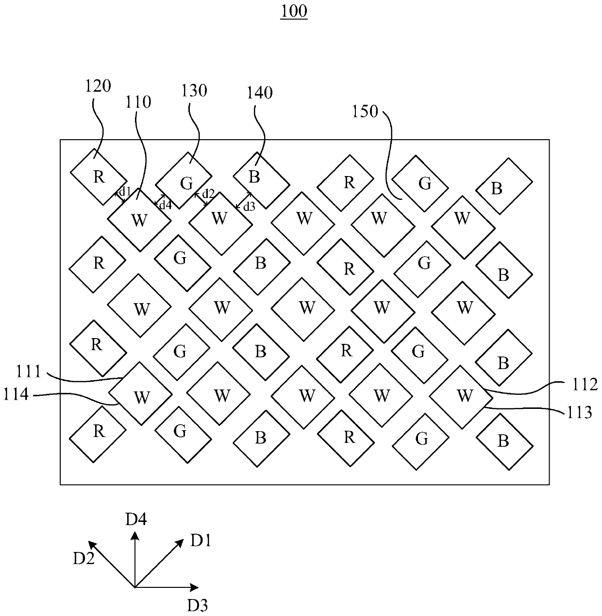
[0020] see figure 2 , figure 2 It is a structural schematic diagram of a color filter substrate in a preferred embodiment of the present invention. The color filter substrate 100 includes a plurality of white color-resist units 110 , a plurality of first-color color-resist units 120 and a plurality of second-color color-resist units 130 . The plurality of white color-resist units 110 are distributed in rows and columns. The white color-resist unit 110 is ...


PUM


Abstract

The invention provides a color film substrate and a display panel. The color film substrate comprises a plurality of white color resistance units, a plurality of first color resistance units and a plurality of second color resistance units, wherein the plurality of white color resistance units are distributed in rows and lines, are rectangular and comprise first edges and second edges which are crossed, the first color resistance units are right opposite to the first edges of the white color resistance unit in the number n row and number m line, the distance from the edge, nearest to the first edge of the white color resistance unit in the number n row and number m line, of the first color resistance unit to the first edge of the white color resistance unit in the number n row and number m line is the first distance, the second color resistance units are right opposite to the second edge of the white color resistance unit in the number n row and number m line and the first edge of the white color resistance unit in the number n row and number (m+1) line, the distance from the edge, nearest to the first edge of the white color resistance unit in the number n row and number (m+1) line, of the second color resistance unit to the first edge of the white color resistance unit in the number n row and number (m+1) line is the second distance, and the first distance is not equal to the second distance.

Description

technical field [0001] The invention relates to the field of flat display, in particular to a color filter substrate and a display panel. Background technique [0002] The principle of RGBW liquid crystal display technology is to add a white (W) sub-pixel to the traditional RGB pixel composed of red (R) sub-pixel, green (G) sub-pixel and blue (B) sub-pixel. Then the corresponding sub-pixel imaging technology is applied, and these sub-pixels are better arranged in the way that the observer sees the image, so as to ensure that the power and brightness of the LCD screen will not be lost when generating an image that is not seen by the human eye. Utilizing white sub-pixels enables an increase in white brightness without increasing power consumption. [0003] Glasses-free stereoscopic display technology has become a development trend of stereoscopic display technology because it does not need to wear traditional glasses and is closer to people's daily habits. The naked-eye ster...

Claims


Application Information

Patent Timeline
Patent Type & Authority Patents(China)
IPC IPC(8): G02F1/1335
Inventor 谢畅
Owner WUHAN CHINA STAR OPTOELECTRONICS TECH CO LTD
Why Eureka
Try Eureka