
Onsite time test device based on satellite common-view technology and method

A technology for testing devices and devices under test, applied in radio-controlled timers, instruments, etc., can solve problems such as incomplete traceability links, satellite time effects, inaccurate standard time, etc., to achieve completeness and ensure accuracy , the effect of improving time accuracy

Active Publication Date: 2016-09-28
CHINA ELECTRIC POWER RES INST +1
View PDF6 Cites 6 Cited by
  • Summary
  • Abstract
  • Description
  • Claims
  • Application Information

AI Technical Summary

Problems solved by technology

[0003] However, figure 1 and figure 2 There are three defects in the method shown in: First, in many cases, the on-site time of the device under test is also received from the satellite time, and one of the main reasons for the inaccurate on-site time is that the poor site conditions produce multi-path Effect has an effect on the satellite time
At this time, if the existing time test device that directly receives the satellite time as the standard time is used, the time of the device will also be affected by the multipath effect, resulting in inaccurate standard time, which in turn will cause large errors in the test results
Second, the direct reception of satellite time belongs to one-way time service, and the theoretical accuracy of time service is only about 400ns. Therefore, if the test device adopts the method of directly receiving satellite time, it will not be able to test field equipment with an accuracy better than 400ns. Many field devices requiring accuracy better than 400ns
The current test method, the test device obtains the time from the satellite, and does not link the test result with the standard time, resulting in an incomplete traceability link

Method used


Image

  • Onsite time test device based on satellite common-view technology and method
  • Onsite time test device based on satellite common-view technology and method
  • Onsite time test device based on satellite common-view technology and method

Examples


Embodiment Construction

[0038] Exemplary embodiments of the present invention will now be described with reference to the drawings; however, the present invention may be embodied in many different forms and are not limited to the embodiments described herein, which are provided for the purpose of exhaustively and completely disclosing the present invention. invention and fully convey the scope of the invention to those skilled in the art. The terms used in the exemplary embodiments shown in the drawings do not limit the present invention. In the figures, the same units / elements are given the same reference numerals.

[0039] Unless otherwise specified, the terms (including scientific and technical terms) used herein have the commonly understood meanings to those skilled in the art. In addition, it can be understood that terms defined by commonly used dictionaries should be understood to have consistent meanings in the context of their related fields, and should not be understood as idealized or over...


PUM


Abstract

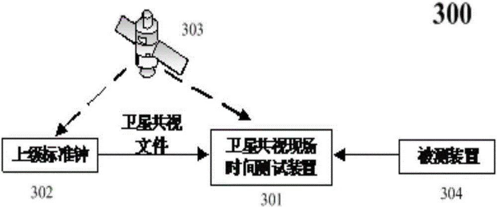
The invention provides an onsite time test device based on the satellite common-view technology and a method. Through satellite common-view with an upper level standard clock, the accurate device time is acquired, taking the accurate device time as reference, accuracy of the onsite time of a tested device is measured. Compared with the prior art, an error of the satellite time because of a multi-path effect is eliminated, measurement accuracy is improved, and integrity of a tracing link is further guaranteed. The device comprises a device clock module used for determining the time of an onsite time test device, a satellite common-view module used for receiving a satellite signal and generating a test device common-view file, a communication module used for receiving a standard clock common-view file sent by the standard clock, a calibration module used for comparing the result calibration device time according to the common-view file, a test interface used for receiving a tested time signal, a test module used for measuring a difference value of the time of the tested device and the standard time, and a display and storage module used for storing the result and displaying the result in real time.

Description

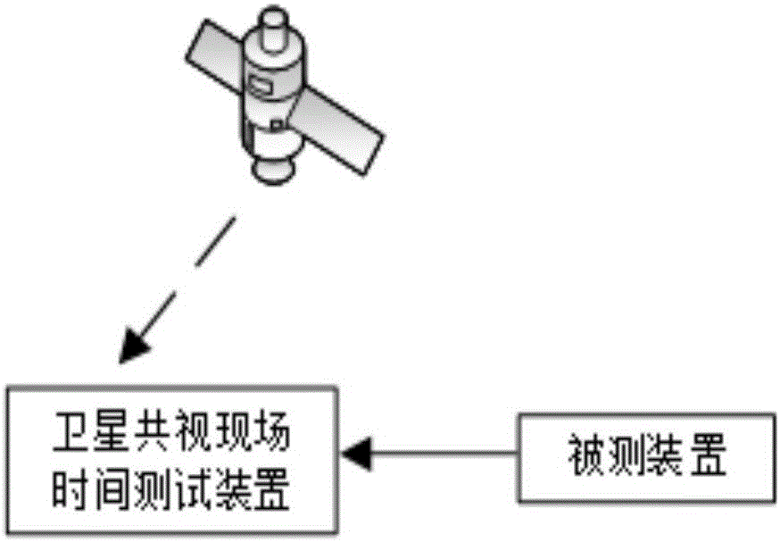
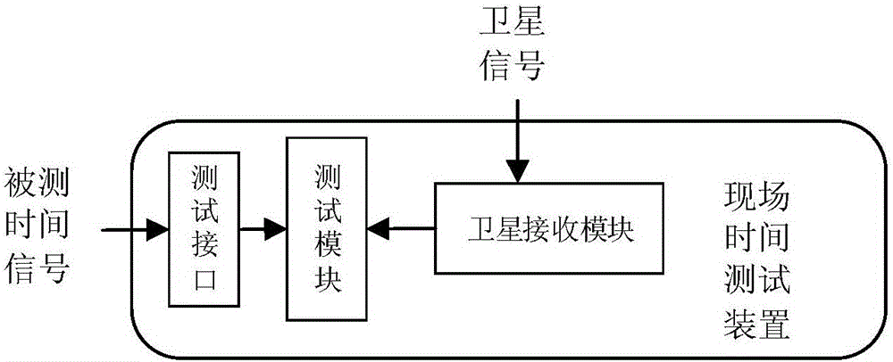
technical field [0001] The present invention relates to the field of time testing, and more particularly, relates to an on-site time testing device and method based on satellite common viewing. Background technique [0002] Currently, there are some field time testing devices on the market, the working principle of these existing devices is as follows: figure 1 shown. The satellite common-view field time test device in the prior art tests the time of the device under test based on the time signal sent by the satellite. In addition, the device structure of the existing on-site time measuring device is as follows figure 2 shown. The working method of the existing on-site time measurement device is: after the time test device is brought to the scene, firstly, the satellite receiving module receives GPS or Beidou satellite signals, and obtains the satellite time as the standard time of the test device; secondly, the device under test The on-site time signal is connected to ...

Claims


Application Information

Patent Timeline
Patent Type & Authority Applications(China)
IPC IPC(8): G04R20/02
CPCG04R20/02
Inventor 卢达赵莎林繁涛白静芬陈松方
Owner CHINA ELECTRIC POWER RES INST
Learn More